uTmax6 · Volume 5
uTmax6 — Vol 5: A 1000 V Pin-Switch Board
Automatic tube-socket wiring for the uTracer6, compatible with Nick Barton's Matrix protocol
Status: requirements and relay choice. No schematic or board exists yet. When they do, the schematic, PCB files, parts list and firmware will be published here and in the uTmax6 repository as open hardware. Prices and stock below are distributor snapshots from November 2026; check them before ordering.
5.1 What a pin-switch board does
A tube’s electrodes sit on different socket pins depending on its type: an EL34’s anode is pin 3, a 12AX7’s first anode is pin 1. The uTracer has one output for each function: anode, screen, grid, cathode and the two heater lines. Something has to connect each socket pin to the right function before a test.
Usually that is a set of patch leads or rotary switches. A pin-switch board does it with relays: the software looks the tube up in its library and closes the right relays itself, so there is nothing to patch and nothing to get wrong.
5.2 Nick Barton’s Matrix board
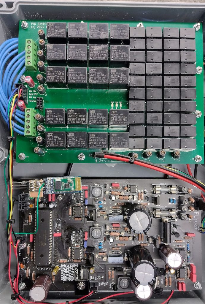
Nick Barton’s Matrix board above a uTracer. Photo: Nick Barton, Black Magic Amplifiers (bmamps.com).
Nick Barton designed the Matrix pin-switch board in 2022 and sold a small number, assembled and tested (bmamps.com). Its design is the starting point for this one:
- It listens on the serial line. The board sits between the computer and the uTracer, so every command passes through it on the way. It acts on one extra command and passes everything on. The uTracer ignores the extra command.
- The command,
SetPins, is 20 bytes: the two bytes80and81(hex), the textSetPins=, then one digit for each socket pin 1 to 10:0open,1anode,2screen,3cathode,4grid,5heater A,6heater B. For a 12AX7 the command endsSetPins=1435624300. The board never replies. - It is a full crosspoint: one relay for every pin and function, 10 × 6 = 60 relays. In his photos, 20 are large HKE HRS4 relays (most likely the heater lines, which carry the most current) and 40 are smaller ones.
- His uTmax drives it. uTmax 3.04 and later send each tube’s pinout from the library automatically when a box in the options is ticked.
Three things mean it can’t simply be bought or copied for a uTracer6:
- It is no longer available. The shop page is gone and the bmamps site says the workshop is closed. A uTracer group member wrote in 2024 that the boards were not available (uTracer group).
- It was never released as open hardware. No schematic, parts list or PCB files were published, and the board is marked “(c) 2022”. So this design is a new one. It reuses the protocol (so it works with Nick Barton’s uTmax 3.04+ as well as uTmax6) and the crosspoint idea, both credited to him, and nothing of his layout, schematic or firmware.
- It looks sized for the uTracer3. His page gives no voltage rating. The HKE HRS4 relay is rated for 750 V AC between open contacts (HRS4 data sheet), about 1060 V peak. A heater relay’s open contact sees the full anode voltage whenever its pin is the anode, so at the uTracer6’s 1000 V there is no margin.
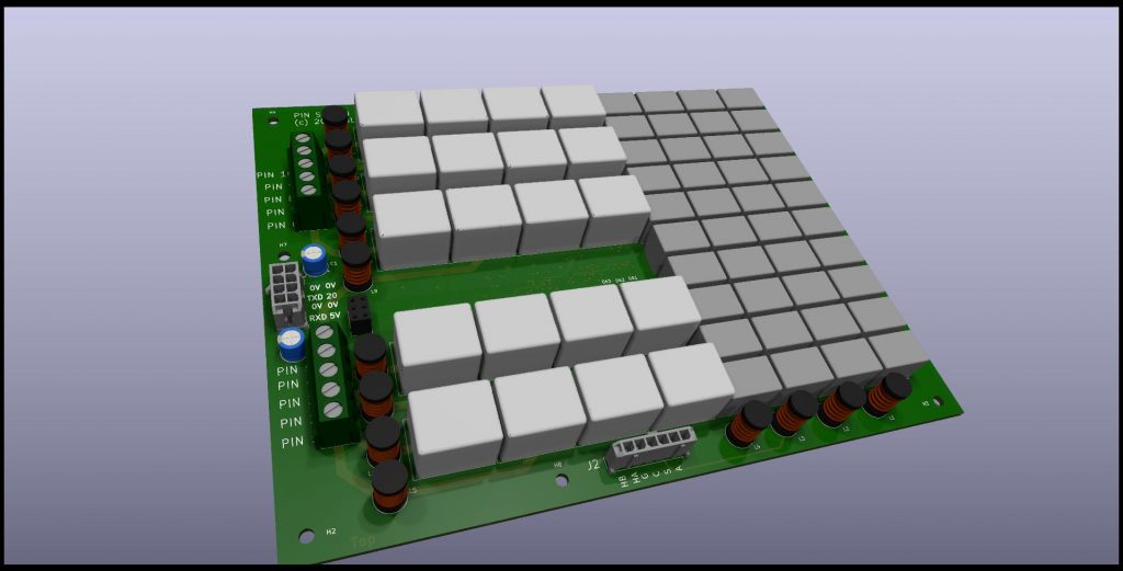
Render of the Matrix board. Nick Barton, bmamps.com.
5.3 Requirements for 1000 V
Table 1 — Requirements for 1000 V
| # | Requirement | Why |
|---|---|---|
| R1 | At least 1.5 kV across open contacts (DC) | Any open contact can see the full anode voltage, 1000 V, plus margin. |
| R2 | At least 1.5 kV from coil to contacts, preferably 3 kV | The coils are driven from low-voltage logic. |
| R3 | Carry at least 1 A in ~1 ms pulses on the anode, screen, grid and cathode lines | The uTracer6’s peak current. |
| R4 | Heater lines carry up to 1.5 A continuously | The uTracer6’s heater maximum (Dekker, §12). |
| R5 | Low contact resistance on heater lines | Every 0.1 Ω drops the heater voltage. |
| R6 | Switched only with the high voltage discharged | Closing a relay onto a charged 25 J reservoir would weld it shut. |
| R7 | In production and stocked; 5 V or 12 V coils | Others must be able to build it. |
R6 is not optional. Relay makers warn that at high voltage, stray capacitance produces current spikes that damage contacts (Pickering 67/68 data sheet). Switching cold also means the relays only ever carry current, never make or break it, which is why small reed relays can do the job.
5.4 The relays
High-voltage reed relays meet these requirements; ordinary signal relays do not (TE’s IM series is rated 1000 V rms and Panasonic’s TX-S 750 V rms across open contacts).
Table 2 — The relays
| Relay | Across contacts | Coil to contacts | Carry | Contact resistance | Coil |
|---|---|---|---|---|---|
| Standex-Meder SHV05-1A85-78D4K | 4 kV DC | 4 kV DC | 2.5 A | 150 mΩ max | 5 V, 140 Ω (36 mA), diode built in |
| Pickering 104-1-A-5/3D | 3 kV DC | not given as a voltage (10¹² Ω) | 1.5 A | 150 mΩ | 5 V, 220 Ω (23 mA) |
| Pickering 67-1-A-12/1D | 5 kV | not given as a voltage | 3 A | 120 mΩ | 12 V, 150 Ω (80 mA); 58 mm long |
Sources: Standex SHV data sheet, Pickering Series 104, Pickering Series 67/68.
The leading choice is the Standex SHV05-1A85-78D4K on all 60 positions. It is the only one of the three with a stated coil-to-contact rating, and that rating is 4 kV. It carries 2.5 A, enough for the uTracer6’s 1.5 A heater, so one part number serves the whole board. The drawbacks: it costs roughly USD 9–16 each (so USD 550–950 for 60), and stock was thin in November 2026 (one distributor showed none, with an 11-week lead time). The Pickering 104 is the alternative if its coil-to-contact isolation can be confirmed with the maker.
Heater drop. At 1.5 A, two 150 mΩ contacts (heater A and heater B) drop 0.45 V, which matters on a 6.3 V heater. The options are to set the heater voltage a little higher to compensate, to measure it at the socket, or to use the Pickering 67 (120 mΩ) for the 20 heater positions.
5.5 How the board will work
 from the computer ──► [ serial in ]──► microcontroller ──► [ serial out ] ──► uTracer6
                                           │   passes every byte on
                                           │   acts on "SetPins=..."
                                           ▼
                            8 × TPIC6B595 shift registers (64 outputs)
                                           │  output enable held OFF unless
                                           │  the HV detector says "discharged"
                                           ▼
          60 reed relays: socket pins 1–10  ×  anode, screen, grid, cathode, heater A, heater B
                                           ▲
HV detector on the anode and screen lines- Drivers: eight TI TPIC6B595 shift registers in a chain give 64 outputs at up to 150 mA each, with built-in clamps for the coil kick-back (TI). The SHV coils draw 36 mA.
- A hardware lock-out. A small detector on the anode and screen lines holds the drivers’ output-enable off while either is above about 20 V. Then no command, correct or corrupted, can change a relay while the reservoirs are charged. The new pattern is loaded into the shift registers but only applied once the lines are discharged.
- Holding the uTracer until the relays settle. Because the board sits in the serial line before the uTracer, it can delay passing on the next command until its relays have settled (about 1 ms for the SHV) and it has read the pattern back. The computer needs no change for this.
- Read-back. The board checks that the coils it energised are the ones it meant to, before it lets commands through.
- A checked command, as an option. Nick Barton’s
SetPinsframe has no checksum. The board will accept it as it is, for compatibility, and will also accept an extended frame with a checksum, which uTmax6 will use. A relay pattern that can put 1000 V on any pin deserves that. - Spacing. At 1000 V the IPC-2221 spacing for uncoated outer layers is 5.0 mm, 2.33 mm with conformal coating, and 1.5 mm on inner layers. The board will route each pin’s net on one side of its relays and each function bus on the other, with slots between the high-voltage buses and the coil wiring, and will be conformally coated.
5.6 Open questions
- When does uTmax send
SetPins? Only before a sweep, or also between curves? That code is in Nick Barton’s unpublished 3.04+ source. The hardware lock-out makes the board safe either way; uTmax6 will send it only with the high voltage discharged. - Directly heated tubes, where the filament is also the cathode:
SetPinsallows one function per pin. Probably the cathode is tied to one heater leg on the cartridge, but this needs working out. - The uTracer6’s heater return: grounded or floating? It decides whether the heater B relays could be simplified.
- Live stock and price for the SHV and Pickering parts.
5.7 What comes next
- Settle the relay (samples of the SHV05 and Pickering 104).
- Draw the schematic; publish it here for comment.
- Lay out the PCB; build one; insulation-test every pin to every other pin and to the coil side at 1.5 kV with all relays open.
- Write the firmware; publish it in the uTmax6 repository.
- Add
SetPins(and the checked frame) to uTmax6.
Comments (0)