uTmax6 · Volume 4
uTmax6 — Vol 4: Dummy Loads
Resistor, diode and MOSFET stand-ins for a tube, for testing a uTracer6 up to 1000 V
Status: design, not yet built or tested. Part ratings below are taken from the makers’ data sheets and cited. Where a figure was read from a graph, or a part number still needs checking against the maker’s ordering table, it says so. This page will be updated with measurements once the loads are built.
4.1 What dummy loads are for
A dummy load stands in for a tube, so a curve tracer can be run before a valuable tube is connected. For uTmax6 they do three jobs:
- First power-up of the uTracer6. If something is wrong, a resistor costs pennies; a tube or the uTracer6’s high-voltage switch costs much more.
- Checking the software’s arithmetic. A precise 100 kΩ resistor at 100 V draws exactly 1 mA. If the program shows anything else, the conversion is wrong. Ronald Dekker checks his own uTracers this way: with a box of 0.1 % resistors he found his sense resistor was 17.8 Ω rather than 18, and corrected it (dos4ever, uTracer3 log §16).
- Comparing the simulator with the bench. The software uTracer (Vol 3) models the same resistor and diode loads, so a simulated run and a bench run can be compared number for number. Any difference points at the simulator, the software or the hardware, and the size of it usually says which.
4.2 The numbers that size the loads
- The uTracer6 pulses up to 1000 V and 1 A for about 1 ms from a 50 µF reservoir (Dekker, uTracer6 log).
- Energy per pulse into a resistor R at voltage V is V²·t/R:
Table 1 — - Energy per pulse into a resistor R at voltage V is V²·t/R
| Load at 1000 V | Peak current | Peak power | Energy per 1 ms pulse |
|---|---|---|---|
| 1 MΩ | 1 mA | 1 W | 1 mJ |
| 100 kΩ | 10 mA | 10 W | 10 mJ |
| 10 kΩ | 100 mA | 100 W | 0.1 J |
| 1 kΩ | 1 A | 1 kW | 1 J |
- Average power is small. Each point waits for the reservoir to recharge through a boost converter fed from 19.5 V, so even the 1 kΩ load dissipates only a few watts on average. The resistors have to survive the pulse, not a kilowatt of heat.
- The worst case is a fault: a failed switch dumps the whole reservoir, ½ · 50 µF · (1000 V)² = 25 J, into whatever is connected.
- The cathode terminal is not at ground. It sits at the supply voltage, +19.5 V, so the anode reaches +1019.5 V relative to the uTracer’s 0 V. The load box must float: no load node may be tied to its case or to mains earth.
4.3 Two kinds of load
- Calibration loads: precise (1 %) and used at modest current, for checking conversions.
- Power loads: rated for pulse energy and fault dumps, for checking the current limit and what happens near 1 A. Their tolerance is poor, so they are not used for calibration.
4.4 The resistors
Table 2 — The resistors
| Family | What matters here | Data sheet |
|---|---|---|
| Vishay VR37 (metal glaze) | 100 kΩ–33 MΩ; 0.5 W; 3500 V maximum | Vishay 28907 |
| Vishay PR03 (power metal film) | 3 W; 750 V continuous; repetitive pulses of 2000 V at 1 ms; about 80–100 W per 1 ms pulse (read from the maker’s graph, roughly ±30 %); 1 % available | Vishay 28729 |
| Ohmite OY (ceramic composition) | 2 W; 400 V working; 80 J single pulse; survives 1640 V from a 52 µF capacitor, almost exactly a uTracer6 reservoir; 10 % only, large temperature coefficient | Ohmite OW/OX/OY |
| Vishay AC05 / AC10 (cemented wirewound) | 5 W / 10 W; limiting voltage √(P·R) | Vishay 28730 |
The Ohmite OY is the part for anything that might take a fault dump. The others are for accuracy.
4.5 The set
One bank for the anode and an identical bank for the screen, each chosen with a switch rated for the voltage. “2×” means two resistors in series, which shares the voltage between them.
Table 3 — The set
| Load | Purpose | Build | At 1000 V | Each part sees |
|---|---|---|---|---|
| 1 MΩ | Low currents; the amplifier’s highest gains | 1 × VR37, 1 MΩ, 1 % | 1 mA | 1000 V of 3500 V |
| 100 kΩ | Dekker’s check: 100 V gives 1 mA | 2 × PR03, 49.9 kΩ, 1 % | 10 mA, 10 W | 500 V of 750 V |
| 10 kΩ | Dekker’s 10 kΩ switch test; 100 mA at 1 kV | 4 × PR03, 2.49 kΩ, 1 % | 100 mA, 100 W | 250 V and 25 W per 1 ms pulse |
| 1 kΩ, power | 1 A at 1 kV; trips the default current limit | 3 × Ohmite OY331KE (330 Ω) | 1 A, 1 kW, 1 J | about 333 V, 0.33 J of 80 J |
| 500 Ω, power | Dekker’s own current-limit test (uTracer6 log, Fig. 10.2) | Ohmite OY string to about 500 Ω (2 × 220 Ω + 56 Ω; check the OY ordering table for those values, then measure the string) | about 1 A at 500 V | under 400 V each |
Notes:
- Current limit. With the default 4.7 Ω sense resistor, the highest current
limit the uTracer6 can set is about 3.6 V / 4.7 Ω = 766 mA, and its hard limit is
about 1.1 A (Dekker, uTracer6 log §10).
The 1 kΩ and 500 Ω loads are there to show the limit trip correctly: status
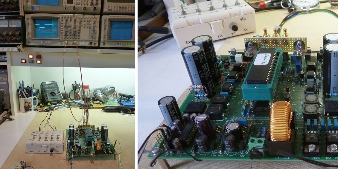
11from the uTracer, and the point dropped from the curve. - Dekker’s own loads. For the uTracer3 he used 1 MΩ, 100 kΩ, 10 kΩ and 1 kΩ in 0.1 % resistors, one set each for anode and screen. For the uTracer6 he used a “resistor box” of 500 Ω, 1k, 2k, 4k and 8k to set currents in binary steps, and every beta tester’s first run was a resistor test to 1 kV.
- Never test with a dead short. Dekker reports that high-voltage switches occasionally die on hard shorts despite the protection; the uTracer6 adds a fuse that blows on one. Test the limit with the power loads instead.
Ronald Dekker’s uTracer6 test set-up, with his resistor box (the white box with toggle switches) beside the board. Photo: Ronald Dekker, uTracer6 log, Fig. 10.4 (left part of the figure).
4.6 Grid and heater loads
- Grid, negative. Leave the grid open and measure it with a meter, or load it with at least 100 kΩ (1 mA at −100 V). Always put 4.7–10 kΩ in series with the grid, as Dekker recommends: the grid amplifier (an LTC6090) does not survive a grid-to-cathode short, and its output is limited to about 90 mA (LTC6090 data sheet).
- Grid current (positive-grid board only): 1 kΩ (100 mA at +100 V) and 10 kΩ (10 mA) PR03 resistors. Put them on a separate switch position that can’t be selected while the grid is negative: 1 kΩ on −100 V would ask for 100 mA, more than the grid amplifier can give.
- Heater. The heater output is continuous PWM, not pulsed. 22 Ω stands in for a 6.3 V / 0.3 A heater and 82 Ω for a 12.6 V / 0.15 A one. Mind the limiting voltage √(P·R): a 5 W 22 Ω part is good only to about 10.5 V, and 19.5 V by mistake into 22 Ω is 17 W. Use a 10 W part (good to 14.8 V) or a 25 W chassis resistor, plus a fuse. Read the heater with a true-RMS meter; an averaging meter reads the PWM wrongly.
- Diode. A 1000 V rectifier (UF4007 or 1N4007) in series with 10 kΩ shows one-way conduction and a knee at about 0.7 V. (The 1N4007’s 1000 V rating is from common knowledge here, not yet a data sheet.)
4.7 A load that behaves like a tube
Resistors make straight lines. To test curve families, the grid controls and the model fitting, a load whose current depends on the grid voltage is needed. A depletion-mode MOSFET fits: like a tube, it conducts with zero bias and a negative voltage on its gate pinches it off.
The candidate is the IXYS IXTP08N100D2: 1000 V, more than 800 mA at zero gate voltage, and cut-off between −2 and −4 V (data sheet).
Suggested circuit, worked out on paper but not built or tested:
- Drain: anode terminal → about 2.4 kΩ (two Ohmite OY 1.2 kΩ) → drain. This limits the current to at most 417 mA, under the current limit. The FET’s worst case is about 104 W for 1 ms at around 500 V, which looks inside its 1 ms safe operating area but without much margin, so keep the current limit on.
- Source: cathode terminal → 10–47 Ω → source. This softens the curves.
- Gate: grid terminal → 4.7 kΩ (Dekker’s series grid resistor) → a 10:1 divider (90 kΩ to the gate, 10 kΩ from gate to source). Then 0 to −40 V on the grid sweeps the gate from 0 to −4 V, covering the cut-off spread. A 15 V Zener and a 100 Ω gate resistor protect the gate.
- Result: a family of anode-current curves stepped by grid voltage, with pentode-like flat tops, and a transfer curve cutting off around −20 to −40 V on the grid.
4.8 Building the box safely
- Float the box. Insulating case, or an earthed metal case with every high-voltage part kept well clear of it. No load node to the case.
- Jacks: shrouded 4 mm sockets rated for 1000 V, such as the Stäubli SAB4-G (1000 V CAT II; data sheet). No 2 mm jack rated for 1 kV was found.
- Spacing: keep at least 8 mm between high-voltage nodes on FR-4 board (creepage for 800–1000 V, pollution degree 2, material group III), or wire the resistors in the air on standoffs.
- Switch: a rotary switch rated for at least 1 kV between positions. Never turn it during a sweep.
- Leads: silicone test-lead wire rated at least 1 kV, with fully shrouded plugs.
- Discharge: disconnect only after the uTracer6’s HV lamp is out (it goes out below about 32 V; discharge continues to 24 V). The resistors hold no charge.
- Labels: high-voltage warnings on the lid and at the jacks.
4.9 Tests to run with them
In order, each one only after the one before passes:
- Simulator only. The same sequence with the software uTracer and the matching load: these runs are the expected results.
- 100 kΩ, up to 100 V. Expect 1.00 mA at 100 V. Adjust the sense-resistor value in the calibration if not, as Dekker did.
- 10 kΩ, up to 200 V. Dekker’s switch test: a straight line, 0–20 mA. A shorted switch gives one or two points and then a time-out.
- 1 MΩ and 100 kΩ, up to 1000 V. Straight lines to 1 mA and 10 mA.
- 1 kΩ power load. The current limit should trip; uTmax6 should drop the point and report it.
- Diode and MOSFET loads. Compare the curve shapes with the simulator’s.
Results will be added here, with the simulator’s numbers beside the bench’s.
Comments (0)