uTmax6 · Volume 3
uTmax6 — Vol 3: The Software uTracer
A simulator that lets anyone run and test uTracer software without the hardware
3.1 Why a simulator
Testing a program that drives 1000 V pulses on a real instrument is slow and risky. A wrong command can put a full kilovolt where a few volts were meant. The uTracer6 here isn’t even built yet. So the first tool built for uTmax6 is a software uTracer: a small program that behaves like the real instrument on a virtual serial port.
It is useful well beyond uTmax6:
- Learn uTmax without a uTracer, or before building the kit.
- Test changes to any uTracer program without risking a tube or the board.
- See exactly what a host program sends, command by command, decoded into volts.
- Check how a program copes with faults: no reply, a corrupted reply, a current-limit trip.
It is plain Python 3 with nothing extra to install, and it runs on Linux,
including the Raspberry Pi, and on macOS. Windows support is planned. The code and
its guide are in the uTmax6 repository, in
tools/utracer_sim/.
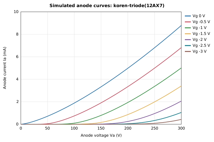
The 12AX7 curves the simulator’s triode load produces, using Norman Koren’s
published model and parameters. These are what uTmax should draw when it sweeps
the simulator with --load triode:12AX7. Drawn by
tools/utracer_sim/plot_curves.py.
3.2 What it has already found
On its first day, the simulator and the tests built on it found a serious bug in
uTmax 3.01. On a uTracer6, asking for a positive grid voltage sends a command
that sets the grid to +100 V. uTmax works out the grid word as a negative
number, prints it as eight hex digits instead of four, and the command is cut off
at its fixed length of 18 characters. For +1 V on the grid, the uTracer6 receives
FFFF in the grid field, which Ronald Dekker’s firmware reads as the full
+100 V, and the heater setting is lost as well. A positive grid needs Dekker’s
extension board, which is probably why it hasn’t been noticed: with that board
fitted, every reply is 4 characters longer than uTmax expects. The grid bug was
fixed the same day: uTmax6 now builds the grid word exactly as Dekker
specifies (+1 V goes out as 8148), and a test checks every grid voltage from
−150 V to +150 V against the simulator’s model of the uTracer6.
The second bug was confirmed and fixed the same day too. Run against the
simulator with the board fitted (--grid-board), uTmax 3.01 never accepted a
reply: it waited for 38 characters, got 42, timed out, reconnected and asked
again, three times in 26 seconds, and never settled. It would also have missed
a current-limit trip with the board fitted, because it looked for status 11
and the board makes it 91. uTmax6 now reads the status byte first and waits
for the right length, as Dekker’s own program does. The same end-to-end test
runs with and without the board on every change.
It also showed that uTmax’s default uTracer3 anode divider (470 kΩ with 6.8 kΩ) differs from Dekker’s published values (482 kΩ with 6.81 kΩ), so an uncalibrated uTracer3 reads about 2.4 % low. Calibration takes that out, but it shows why the simulator keeps its own hardware numbers.
3.3 How the uTracer talks
Dekker documented the uTracer’s serial protocol in detail on dos4ever.com, and the uTracer6 additions in its construction log. In short:
- The link runs at 9600 baud, 8 data bits, no parity, 1 stop bit.
- The host sends commands of 18 hex characters: a two-digit command code, then four 16-bit words for the anode, screen, grid and heater.
- The uTracer echoes every character as it arrives.
- Two commands get a 38-character reply after the echo:
10, measure, and50, read every analogue channel. The rest get only the echo.
Table 1 — How the uTracer talks
| Code | Meaning | Reply |
|---|---|---|
00 | Settings: current limit, averaging, screen and anode amplifier gains | echo only |
10 | Measure at the given anode, screen, grid and heater settings | 38 characters |
20 | Apply those voltages and hold them | echo only |
30 | End measurement: discharge the reservoir capacitors, grid to zero | echo only |
40 | Heater on or off at the given voltage | echo only |
50 | Read every analogue channel (“ping”) | 38 characters |
The reply carries a status byte (10 for good, 11 if the current limit
tripped), the anode and screen currents before and after their amplifiers, the
anode and screen reservoir voltages, the supply voltage, the negative rail, and
the amplifier gains actually used. On a uTracer6 with the positive-grid board,
the status byte also has its top bit set and the reply grows to 42 characters.
There is no checksum. The echo is the only check, and the host sees it only after the uTracer has acted. That is one reason uTmax6 will check every command before sending it.
3.4 How the simulator works
For each measurement command, the simulator:
- converts the command’s numbers to volts using a hardware profile: the divider and sense resistors, the grid range and the supply voltage of the model being simulated;
- works out what the device under test actually sees: the reservoir voltage, minus the supply voltage (the uTracer’s cathode terminal sits at the supply, +19.5 V on a uTracer6), minus the drop across the current-sense resistor;
- asks the load model what current flows at those voltages, and solves the small loop between that current and the sense-resistor drop;
- checks the current limit the host set. The limit byte goes straight into the
PIC microcontroller’s comparator reference; Dekker’s example,
8Fwith an 18 Ω sense resistor, works out to exactly 200 mA; - picks the amplifier gain the firmware’s auto-range would pick, and sends the reply in the order the protocol defines.
3.4.1 Why the hardware numbers are kept separate
The simulator’s job is to catch mistakes in host programs. If it borrowed its conversion factors from uTmax, it would agree with uTmax’s mistakes. So every hardware constant lives in a profile file with a note of where it came from. Both profiles use Dekker’s published values:
Table 2 — profiles use Dekker's published values
| uTracer3 | uTracer6 | |
|---|---|---|
| Anode and screen divider | 482 kΩ / 6.81 kΩ (0.35 V per count) | 1 MΩ / 4.7 kΩ (1.0448 V per count) |
| Current-sense resistor | 18 Ω | 4.7 Ω (user-changeable) |
| Supply and its divider | 18.5 V; 6.8 kΩ / 1.8 kΩ | 19.5 V; 10 kΩ / 1 kΩ |
| Grid | 10-bit, 0 to −50 V | 16-bit, ±100 V; top bit set for positive |
| Negative rail | boost converter, 47 kΩ / 2 kΩ | −15 V via 47 kΩ / 4.7 kΩ (plus a −85 V rail) |
One uTracer6 detail is still open: it has two negative rails, and which one the reply reports isn’t stated.
3.4.2 Loads
Table 3 — Loads
| Load | What it stands for |
|---|---|
open | Nothing connected |
r:10k | A resistor from anode to cathode |
r:10k,s:47k | Plus a resistor from screen to cathode |
diode:0.7,1k | A diode drop, then a resistor |
triode:12AX7 | Norman Koren’s triode model with his published 12AX7 parameters |
The resistor and diode loads are the same as the physical dummy loads (Vol 4), so a simulated run and a bench run of the same load can be compared number for number.
3.5 Using it
Start it with a 10 kΩ load and a log file:
python3 tools/utracer_sim/utracer_sim.py --load r:10k --log /tmp/sim.jsonlIt makes a serial port and says where:
uTracer simulator: profile=utracer6, load=resistor(anode=10000 ohm)
serial port: /tmp/utracer-sim -> /dev/pts/4
Point uTmax at /tmp/utracer-sim, in the COM= line of ~/uTmax_files/cal.txt
or in its Debug dialog. Every command is logged as one line of JSON, decoded. A
real line:
{"n": 2, "rx": "1000E3000000000000", "cmd": "measure",
 "decoded": {"Va_reservoir_V": 237.17, "Vs_reservoir_V": 0.0, "Vg_V": 0.0, "Vf_Vrms": 0.0},
 "measured": {"Ia_mA": 21.7567, "Is_mA": 0.0, "Va_tube_V": 217.57, "gain_a": 20,
              "gain_s": 200, "averaging": 1, "status": "10"},
 "tx": "1001A200150000000000E30000016B028B0407"}
Anode code 00E3 is 237 V on the reservoir. Less the 19.5 V supply and the drop
across the sense resistor, the 10 kΩ load sees 217.6 V and draws 21.8 mA, and the
auto-range picked an amplifier gain of 20.
3.5.1 Options
Table 4 — Options
| Option | Meaning |
|---|---|
--profile utracer6 | Which model to simulate: utracer6 or utracer3 |
--load SPEC | The device under test (table above) |
--grid-board | Fit Dekker’s positive-grid extension board (uTracer6) |
--log FILE | Write one JSON line per command |
--no-reply-after N | Fault: stop replying after N commands |
--garble-every N | Fault: corrupt every Nth reply |
--trip | Fault: report a current-limit trip on every measurement |
3.6 How it is tested
The simulator is itself checked against Dekker’s figures: full scale of 358 V on
a uTracer3, 1.0448 V per count on a uTracer6, his current formula
(n = 3683 · Ia · gain · samples for 18 Ω), his negative-rail formula, and the
200 mA limit example. Further tests talk to it over a real pseudo-terminal, and an
end-to-end test starts the actual uTmax program with no window and checks, from
the simulator’s log, what it sends: a read of every channel when the port opens,
then the discharge command (30) every 20 seconds while idle.
Whole sweeps. A small test hook in uTmax6 (uTmax --test-sweep <file>) lets a
test do what a person does: pick a tube, set a sweep, press Start. The hook
records every status message and error box, and writes every measured point to
a report when the sweep ends. A test then checks both sides: the voltages the
simulator actually received, and the currents uTmax reported. Into a 100 kΩ load
from 30 to 300 V on a simulated uTracer6, uTmax reports the current to within
0.2 %. Other sweep tests run a delayed sweep to 600 V, the same sweep with the
positive-grid board fitted, and a sweep above the user’s maximum (refused before
anything is sent).
The hook’s very first runs found two more bugs in 3.01. A calibration value
missing from cal.txt is never given a default, so uTmax uses whatever happened
to be in memory: in one run the anode factor came out as −89 254, and uTmax sent
0 V instead of 30 V. The cal.txt that 3.01 creates on a new install has no grid
calibration at all. Second, if the style-sheet file can’t be found, uTmax crashes
on the first point of every sweep (a division by zero in the plot code). The
calibration bug is fixed: every value now starts from a defined default, a new
install’s cal.txt includes the grid calibration, and a test with a partial
cal.txt now sweeps 30-300 V at −2 V on the grid exactly as asked. Before the
fix that same test sent the anode at almost 0 V and the grid at 0 V, and uTmax
still called the sweep done. The style-sheet crash is next.
These tests (46 of them) run automatically on every change, on Linux PCs and on ARM processors like the Raspberry Pi’s. Every fix follows the same rule: make the bug happen in a test first, fix it, then put the old code back in a scratch copy and check that the test catches it.
3.7 Limits, for now
- Linux and macOS only.
- The drop in reservoir voltage during a pulse (up to 20 V at 1 A) isn’t modelled yet.
- Auto-averaging follows the rule uTmax assumes; the firmware’s own rule is still to be checked.
- Nick Barton’s own firmware commands, for his replacement uTracer3 chip, are logged but not answered.
Comments (0)