uTmax6 · Volume 2
uTmax6 — Vol 2: Progress
What is done and what comes next
This page is copied from
docs/PROGRESS.mdin the uTmax6 repository, so GitHub and this site always show the same list.
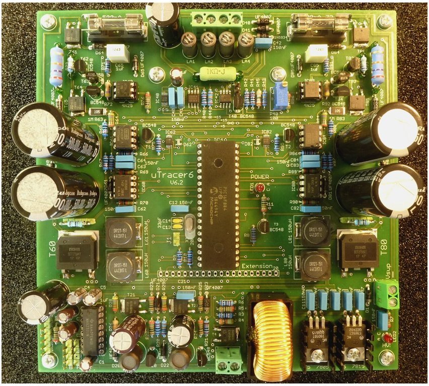
The hardware uTmax6 is written for: a uTracer6 (V6.2) board. Photo: Ronald Dekker, uTracer6 log, Fig. 7.4 (left part of the figure).
What has been done on uTmax6, and what comes next. Newest first in each list. The
reasons behind the order are in PLAN.md; every code change is
described in CHANGES.md.
Last updated: 2026-11-18
2.1 The software uTracer at work
The simulator (tools/utracer_sim/) is built, tested and in daily use. It
pretends to be a uTracer3 or uTracer6 on a virtual serial port, answers Ronald
Dekker’s protocol character for character, models a resistor, diode or 12AX7
load, can misbehave on purpose (no reply, garbled reply, current-limit trip, the
positive-grid board’s longer replies), and logs every command it receives,
decoded into volts.
How it is used. Every change to uTmax6 goes through it, three ways:
- Decoding single commands. Small C++ checks build the exact command uTmax would send, and the simulator decodes it as the uTracer would, so an encoding is checked against the instrument, not against itself.
- The real program, idle. uTmax runs with no window against the simulator and the test reads what it sent on its own: the ADC read at start-up and the 20-second heartbeat. Run with and without the positive-grid board.
- The real program, whole sweeps. A test hook (
uTmax --test-sweep) lets a test pick a tube, set a sweep and press Start. The test then checks both sides: what the simulator received (the voltages actually asked for) and what uTmax reported (the currents it measured). Into a 100 kΩ load from 30 to 300 V, uTmax reports the current to within 0.2 %.
The rule for every fix: first make the bug happen in a test, then fix it, then put the old code back in a scratch copy and check that the test fails. All 58 tests run on every push, on Linux x64 and arm64; Windows builds too.
What it has found so far:
Table 1 — What it has found so far:
| Found | How | Status |
|---|---|---|
A positive grid voltage on a uTracer6 was sent as +100 V (+1 V went out as FFFF), and the heater setting was lost | Simulator decoding uTmax’s command | Fixed |
With Dekker’s positive-grid board, uTmax never accepted a reply (42 characters, not 38): it timed out and reconnected over and over; a current-limit status 91 would have been missed | Simulator with the board fitted, real program | Fixed |
| Sweeps with a hold delay stopped above 425 V on a uTracer6; sweeps without a delay had no last-moment check at all | Code comparison with Dean Jenkins’ fork; confirmed with a whole sweep | Fixed; a 600 V delayed sweep now runs end to end |
Calibration values never initialised: a key missing from cal.txt took whatever was in memory (seen: an anode factor of −89 254, and 2.5 × 10³¹), uTmax sent 0 V and still called the sweep done; the cal.txt made on a new install had no grid calibration at all | First whole sweep through the test hook | Fixed |
| Crash on the first point of every sweep when the style sheet can’t be found (a division by zero in the plot code) | First whole sweep through the test hook | To fix |
| uTmax’s default uTracer3 anode divider reads 2.4 % low against Dekker’s published values | Building the simulator’s uTracer3 profile | Recorded; calibration absorbs it |
2.2 Done
-
2026-11-18 — Fixed: calibration values never initialised. Every calibration value now starts from a defined default; a new install’s
cal.txtincludes the grid calibration; a value that can’t be read keeps its default instead of becoming 0. Before the fix, a test with a partialcal.txtsent the anode at 0 V instead of 30-300 V and the grid at 0 V instead of −2 V, and still reported the sweep as done. Now the same test sweeps correctly. -
2026-11-18 — Test hook: whole sweeps in the tests.
uTmax --test-sweepruns one sweep from a settings file and writes a report. Four end-to-end sweep tests: a uTracer6 sweep into 100 kΩ (currents within 0.2 %), a delayed sweep to 600 V, the same sweep with the positive-grid board, and a sweep above the maximum refused before anything is sent. Its first run found two more bugs (uninitialised calibration; a crash without a style sheet). -
2026-11-18 — Fixed: delayed sweeps stopped at 425 V on a uTracer6. Sweeps with a delay refused anything above 425 V, the uTracer3’s ceiling. Every measurement is now checked against the maximum set in the calibration, capped at 425 V on a uTracer3 (as before) and 1000 V on a uTracer6. Sweeps without a delay, which had no such check, now have the same one.
-
2026-11-18 — Fixed: uTmax works with the positive-grid extension board. With Dekker’s board fitted, the uTracer6 answers with 42 characters instead of 38. uTmax 3.01 waited for 38, so it never accepted an answer and kept reconnecting. It now reads the status byte first, as Dekker’s own program does, and also recognises a current limit with the board fitted (
91). Tested end to end against the simulator with and without the board. The grid current is received but not shown yet. -
2026-11-18 — Fixed: positive grid on a uTracer6. A positive grid voltage now goes out as Dekker specifies (+1 V is
8148, notFFFF= +100 V), and the heater setting is no longer lost. Tested against the simulator’s uTracer6 model from −150 V to +150 V. -
2026-11-18 — Decided: a plain, easy-to-build case alongside the steampunk trunk, with room for an optional Raspberry Pi and display.
-
2026-11-18 — Developer manual (
docs/DEVELOPER.md): structure, state machine, a sweep step by step, protocol, conversions, files, simulator, tests, how to make a change. -
2026-11-18 — Found: a positive grid on a uTracer6 sends +100 V. uTmax 3.01 formats a positive grid voltage as a negative number; the command is cut short and the uTracer6 would apply +100 V instead of, say, +1 V. Reproduced and recorded as a test; fix next.
-
2026-11-18 — Simulator’s uTracer6 profile checked against Dekker’s uTracer6 page; positive-grid extension board added (42-character replies).
-
2026-11-18 — Automatic builds pass on Windows as well; Linux runs the tests against the freshly built program on x64 and arm64.
-
2026-11-18 — Decided: keep supporting the uTracer3 and uTracer3+.
-
2026-11-18 — Software uTracer (
tools/utracer_sim/): echoes and answers Dekker’s protocol, models resistor, diode and 12AX7 loads, injects faults, logs every command. Its formulas are checked against Dekker’s published figures. -
2026-11-18 — First end-to-end test: the real uTmax, run without a window, talks to the simulator; its start-up and idle behaviour is recorded.
-
2026-11-18 — Automatic builds pass on Linux x64 and Linux arm64.
-
2026-11-18 — Repository created with Nick Barton’s uTmax 3.01 imported byte-for-byte as the first commit.
-
2026-11-18 — Project file links GSL from the system on every platform; automatic builds on Linux x64, Linux arm64 (Raspberry Pi class) and Windows.
-
2026-11-18 — README, credits (Nick Barton, Dean Jenkins, Ronald Dekker, Norman Koren), change log, build instructions, plan.
-
2026-11-18 — Commit rules: every commit message names every file it changes and says why; a hook in
tools/hooks/checks this. -
2026-11-18 — Compared Dean Jenkins’ uTmax 1.3a fork with 3.01, fix by fix; found the 425 V limit on delayed sweeps.
-
2026-11-17 — uTmax 3.01 confirmed to build unchanged on Linux with Qt 6.
2.3 In progress
- Which negative rail the uTracer6 reports (-15 V or -85 V).
- Design of a 1000 V Matrix relay board to replace Nick Barton’s.
- Dummy-load designs for the first hardware checks.
2.4 Planned
2.4.1 Software
- Simulator: Dekker’s protocol, a tube model, fault injection, command log
- Simulator: uTracer6 constants checked against Dekker’s page
- Simulator: Windows support; reservoir droop
- Tests that drive a full sweep (test hook in uTmax)
- Tests that record 3.01’s present behaviour
- Fix the positive-grid command on the uTracer6
- Handle the positive-grid board’s 42-character replies
- Show the grid current from the extension board
- Allow a positive grid only when the extension board is fitted
- Check every command before sending, treat a bad echo as an error, check replies
- Fix the 425 V limit on delayed sweeps
- Initialise every calibration value; write
Vg0/Vgmin a newcal.txt - Don’t crash when the style sheet is missing
- Send End Measurement (discharge) on Stop and at the end of each sweep
- Stop rewriting
cal.txtat every start - Create
~/uTmax_filesif missing; load styles and write logs there - Sensible new-install defaults for Linux and the uTracer6
- Smaller fixes (see
PLAN.md, stage 4) - Check the uTracer6 conversion constants against Dekker’s schematic
- Move the serial protocol and conversions into their own tested classes
- Touch-screen layout; encoder and buttons
- Matrix SetPins support
- Tube Desk (basing diagrams, wiring lists, data-sheet links)
- Limits and confirmation above about 450 V
- Windows installer / ready-to-run download
2.4.2 Hardware
- Matrix relay board: requirements and relay choice
- Matrix relay board: schematic and PCB
- Matrix relay board: build and 1 kV insulation test
- Dummy-load set: design, build, test
- Plain case: design (stock enclosure, drilling templates, room for an optional Pi and display)
- Plain case: build guide, plus an addendum for fitting the Pi and display
2.4.3 Testing on a uTracer6
- Capture Dekker’s own program on the serial line and compare
- Dummy loads, low voltage
- Dummy loads, up to 1000 V
- Reference tube against Dekker’s program
2.4.4 Documentation
- Simulator guide (
tools/utracer_sim/README.md) - Developer manual, first edition (
docs/DEVELOPER.md); grows with stage 5 - Dummy-load build guide
- Matrix board build guide
- User manual
2.4.5 Other uTracers
- Every test against the uTracer3 profile as well
- Find out whether the uTracer NXT uses the same protocol
- Test builds for uTracer3 owners
2.4.6 Later ideas
- Transistor curve tracing (see
PLAN.md)
Comments (0)