uTmax6 · Volume 1
uTmax6 — Vol 1: The Project
An open, tested and documented uTmax for the 1000 V uTracer6
1.1 What uTmax6 is
uTmax6 is a fork of uTmax, the open-source program that runs Ronald Dekker’s uTracer vacuum-tube curve tracers. Nick Barton wrote uTmax and released it under the GNU General Public License. uTmax6 starts from his version 3.01 and aims to make it a program a uTracer6 owner can trust at 1000 V, on Linux, the Raspberry Pi and Windows.
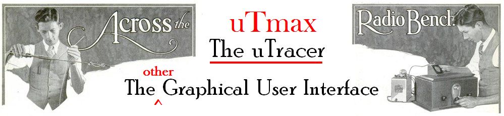
The banner uTmax shows on start-up, from Nick Barton’s uTmax 3.01 source
(src/Themes/img/uTracer_1k.jpg), built around an old “Across the Radio Bench”
magazine heading.
The code is public at github.com/tjscientist-labs/uTmax6. What has been done and what comes next is on the progress page (Vol 2), which is copied from the repository so the two never disagree.
Status, November 2026: early work. The program in the repository is still Nick Barton’s 3.01 with only build changes. uTmax’s uTracer6 mode was written without a uTracer6 to test against, and it has not yet been tested on one here either. My uTracer6 is still being built into its case. Nothing on these pages should be taken as a tested way to run a uTracer6 at high voltage until the hardware checks are marked done.
1.2 Links
Table 1 — Links
| Code | github.com/tjscientist-labs/uTmax6 |
| Developer manual | docs/DEVELOPER.md: how the program works inside, the uTracer protocol, the tests, and how to make a change |
| The plan in full | docs/PLAN.md |
| Every change | CHANGES.md and the commit history |
| Building it | BUILDING.md: Linux, Raspberry Pi, Windows |
| Simulator guide | tools/utracer_sim/README.md, and Vol 3 here |
| User manual | To be written |
1.3 Why fork it
I own a uTracer6 and am building it into a wooden trunk with a Raspberry Pi and a touch screen in the lid. Dekker’s own program runs only on Windows. uTmax builds on Linux, has a tube library and model fitting, and is open source, so it is the natural program for the Pi. Four things stand in the way:
- Its uTracer6 mode is untested. Nick Barton wrote it without the hardware and says so. Some of its constants disagree with his own change notes.
- Some limits are wrong for 1000 V. A sweep that uses the hold delay stops at 425 V (fixed in uTmax6), and new installations start with a 300 V maximum.
- Small bugs that matter on a Pi: the calibration file is rewritten at every start (a needless write to the SD card), the data folder is never created, and the style sheet is read from whatever folder the program was started in.
- No one is maintaining it. Nick Barton’s site says the workshop is closed, and his later versions (3.04 onward, with support for his Matrix relay board) were released as programs but their source was not published.
Dean Jenkins met the same problems in 2017–2018 with uTmax 1.3a, fixed several of them on Linux and documented building it on a Raspberry Pi 4. Nick Barton’s later versions did not take in his changes. uTmax6 carries the ones that still apply forward, credited to him.
1.4 Who did what
Table 2 — Who did what
| Ronald Dekker | Designed the uTracer3, uTracer6 and uTracer NXT, and published their construction and serial protocol at dos4ever.com. |
| Nick Barton (Black Magic Amplifiers) | Wrote uTmax from 2013, added uTracer6 support in version 2.3, and designed the Matrix pin-switch board. bmamps.com: uTmax |
| Dean Jenkins | Maintained a Linux fork of uTmax 1.3a, 2017–2018, with a reworked serial state machine, fixes and Raspberry Pi build notes. github.com/skullandbones/uTmax |
| Norman Koren | The tube model uTmax fits to measured curves derives from his work, used with his permission. normankoren.com |
| uTmax6 | Started November 2026. Code and documentation written with the help of Claude (Anthropic). |
1.5 How the work is done
Nick Barton’s code is the starting point, not a draft to throw away. The first commit in the repository is his 3.01 source exactly as published, byte for byte, so anyone can see every line that has changed since.
Every commit explains itself. Each commit message names every file it changes
and says what changed and why, and a check in the repository refuses a commit that
doesn’t. A plain-language change log (CHANGES.md) records every change to the
program, as the GPL asks.
Nothing changes without a test. The hardware is not built yet, so the program is tested against a software uTracer: a simulator that behaves like the real instrument on a virtual serial port (Vol 3). The tests first record what uTmax 3.01 does today. A fix then changes that recorded behaviour on purpose, and the test shows it.
Say what is untested. Until the hardware checks below are done, every page and the program’s README say plainly that the uTracer6 mode is untested.
1.6 The plan
- Repository and builds. Import 3.01 unchanged; build on Linux, Raspberry Pi and Windows automatically on every change. Done.
- The software uTracer. A simulator that follows Dekker’s protocol, models resistors, diodes and tubes, and can be told to misbehave. Working; its uTracer6 constants still to be checked against Dekker’s schematic.
- Tests that record today’s behaviour. Started.
- Bug fixes, one per commit, each with its own test.
- Reorganise and comment. Move the serial protocol and the voltage and current conversions out of the 4,000-line main window into parts that can be tested on their own. Dean Jenkins’ state machine is the model for the protocol side.
- New features for the uTracer6 trunk: a full-screen touch layout, the case’s knob and buttons, Matrix relay-board support, a “Tube Desk” with basing diagrams and data-sheet links, and a confirmation step above about 450 V.
- Hardware checks, each a gate for the next: the simulator; a comparison with the commands Dekker’s own program sends; the uTracer6 into dummy loads (Vol 4) at low voltage and then up to 1000 V; a known reference tube against Dekker’s program.
- A user manual. Its outline and the parts that won’t change first; screenshots and procedures after the hardware checks.
1.7 The hardware that goes with it
-
A 1000 V pin-switch board (Vol 5). Nick Barton’s Matrix board wires a tube’s socket pins to the uTracer’s anode, screen, grid, cathode and heater lines with relays, so the tube library can set them up. It is no longer sold, it was never published as open hardware, and its relays are not rated for 1000 V. The replacement is a new design that speaks his
SetPinsprotocol, so it works with his uTmax 3.04 and later as well as uTmax6. Its schematic, PCB files and parts list will be published here. -
Dummy loads (Vol 4): resistor and diode networks that stand in for a tube, so the first high-voltage runs risk nothing valuable, and so a simulated run and a bench run of the same load can be compared number for number.
-
A plain case anyone can build. The trunk is one builder’s project; most owners want a box. Alongside it there will be a plain, functional case: a stock enclosure with printable drilling templates, the sockets and a 1 kV patch field on one top plate, an HV lamp, a clear cover and an interlock. It works with any laptop, and has room for an optional Raspberry Pi and display, with an addendum to its build guide for fitting them.
1.8 Later ideas
Transistor curve tracing. The uTracer’s negative grid supply already suits JFETs and depletion-mode MOSFETs, and Dekker’s positive-grid extension (0 to +100 V, with grid-current measurement) looks enough for enhancement MOSFETs. Bipolar transistors are harder: they need stepped base current, not voltage, perhaps through a series resistor from the positive grid supply with the software doing the conversion. Not started; worth exploring once the tube side is solid.
1.9 Licence
uTmax6 is free software under the GNU General Public License, version 3 or later, as Nick Barton released uTmax. There is no warranty. A uTracer6 stores about 25 J at 1000 V in its reservoir capacitors, a potentially lethal amount, and keeps it after the power is switched off.
Comments (0)