TSH-06F IC Tester · Volume 2
TSH-06F IC Tester — Vol 2: How It Tests, and What It Cannot See
A truth-table check at walking pace: good at dead gates, blind to slow ones.
2.1 The method: a static functional test
A logic chip has a truth table. For a 7400, each of the four gates gives a LOW output only when both inputs are HIGH. A functional tester checks the truth table: it powers the chip, drives its input pins with each combination in turn, reads the output pins, and compares them with what the library says they should be. One mismatch and the chip fails.
The TSH-06F works this way. Its manual describes no other kind of measurement for logic parts. Everything below follows from that, and the parts that are inference, not documentation, are marked as such.
What a functional test catches well:
- Dead or stuck outputs. An output that stays HIGH or LOW whatever its inputs do. This is the commonest failure of a TTL gate after a static zap or an overload.
- Open inputs and broken bond wires. On TTL an open input floats HIGH, so the gate gives the wrong answer for any vector that needs that input LOW.
- Shorts between pins. These show up as outputs that follow the wrong input.
- Wrong or remarked parts. A chip relabelled as something it isn’t fails the truth table. In Search mode the tester may even name what it actually is.
- Sequential logic, if the library drives it. For flip-flops (7474), counters and shift registers (7495), the test has to clock the chip through states. A library entry for these is a sequence, not a single table, and how thoroughly each sequence works the chip is not documented.
2.2 What it cannot see
Static functional testers share a set of blind spots. They are worth knowing before trusting a PASS:
Table 1 — Static functional testers share a set of blind spots. They are worth knowing before trusting a PASS
| Blind spot | Why it matters |
|---|---|
| Speed | The test runs at whatever pace the tester’s microcontroller drives its pins, far slower than the chip’s rated speed (inferred: the manual gives no test rate). A gate whose propagation delay has drifted from 10 ns to 40 ns passes here and can still break a circuit with tight timing. |
| Output drive (fan-out) | A good TTL output sinks 16 mA at a guaranteed LOW level. The tester reads the output through a light load, so an output that can only sink 2 mA still looks LOW. In a real board, driving ten inputs, it would not be. |
| Input thresholds and leakage | A weak input that switches at the wrong voltage, or leaks, can read correctly under the tester’s clean drive. |
| Noise margin and supply sensitivity | It tests at one supply voltage (5.0 V or 3.3 V), not at the 4.75 V and 5.25 V edges of the TTL specification. |
| Intermittents and heat | A chip that fails only when warm, or after an hour, passes a two-second test. |
| Parts not in the library | An unknown number reads “Not Found!”. That says nothing about the chip. |
General guides to these testers say the same thing: timing faults can go undetected, and not every type is in the library (IndiaMART IC tester listing, a low-authority seller page; the point is a general property of static testers).
2.3 The 74LS and 74HC menus share one library
The manual says the 74HC and 74LS menus hold the same part list with a “different driver circuit”. The truth tables are identical; only the way the tester drives the pins changes, to suit TTL or CMOS input behaviour.
That leaves three practical questions for anyone testing older parts. Vol 3 answers each one with a known-good chip, not a guess:
- Standard TTL (7400, not 74LS00). There is no “74” menu. A standard-TTL input sources about 1.6 mA when pulled LOW, four times a 74LS input. The tester’s drivers probably manage that (inferred: microcontroller pins usually sink well over 1.6 mA), so standard TTL should test under the 74LS menu. That is not documented, so it needs a check.
- Open-collector outputs (7403, 7405, 7406, 7416). These outputs can only pull LOW. HIGH needs a pull-up resistor, which the tester may or may not supply. If it doesn’t, a good open-collector chip reads as stuck LOW, or as random. The manual is silent, so this needs a check too.
- Same number, different chip. A few standard-TTL types do not share a pinout with the 74LS part of the same number. The library is built on the 74LS/74HC versions, so testing the standard part under its LS number can fail a good chip. Texas Instruments’ data sheet shows the 7451 as two 2-wide, 2-input AND-OR-INVERT gates, but the 74LS51 has one 3-input section, and its pins are assigned differently (TI SN7451/SN74LS51 data sheet, SDLS113, 1988; Library copy). The 7454 and 74LS54 also differ in gate arrangement (see the KENBAK-1 parts list in Iconic Machines). Both are on the KENBAK-1 board.
2.4 What’s inside
I opened mine. Four screws hold the board to the front half of the case, behind the LCD, socket and keys. The back half holds the two-AA battery box, wired to the board through a two-pin plug, and a six-conductor flat tail from the keypad plugs into the back of the board.
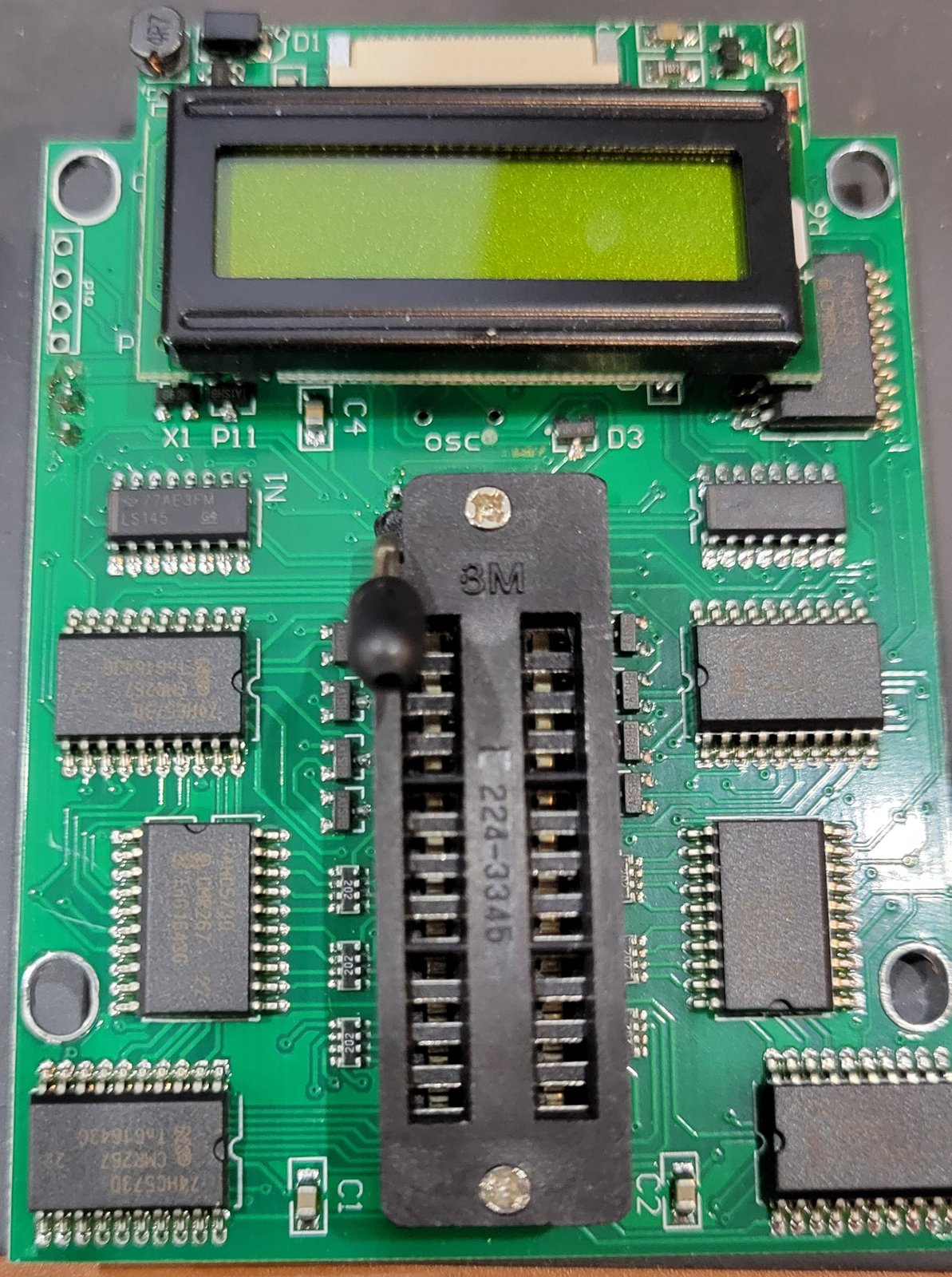
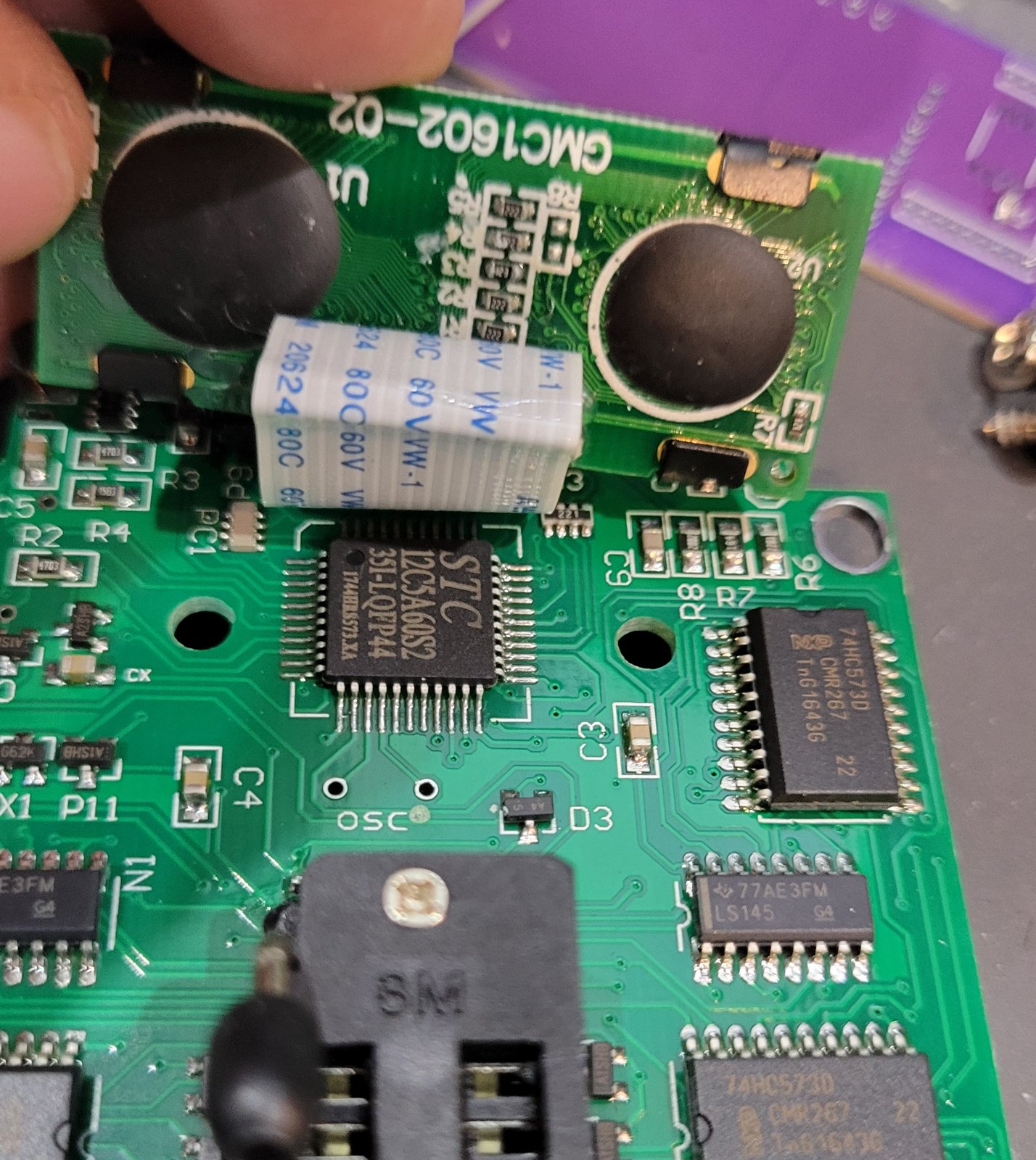
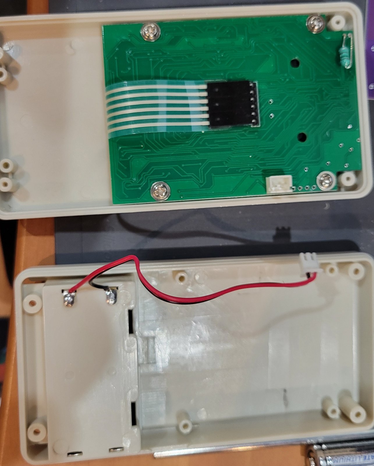
The parts, read from their markings:
Table 2 — The parts, read from their markings
| Part | Marking | What it is |
|---|---|---|
| Microcontroller | STC 12C5A60S2, LQFP-44 | STC Micro’s 8051-compatible microcontroller, 60 KB flash, with an ADC (probably what reads the battery voltage) |
| Latches | 74HC573D (NXP), ×7 | Octal latches: 56 latched outputs, enough to drive 24 socket pins plus the control lines (role inferred) |
| Decoders | LS145 (TI), ×2 | 74LS145 BCD-to-decimal decoders with open-collector outputs (role not traced) |
| MOSFETs | A1SHB, SOT-23, ×8 (four each side of the socket) | SI2301-type P-channel MOSFETs (LCSC: SI2301, marking A1SHB), most likely the switches that put 5 V on whichever pin a chip uses for VCC (inferred) |
| Resistor arrays | 202, ×6, beside the socket | 4 × 2 kΩ each, so 24 resistors: one per socket pin |
| Boost converter | 4R7 inductor, SS14 Schottky diode, a 6-pin SOT-23 controller | The boost converter: two AA cells give 3 V at best, and the chips under test run at 5.0 V |
| Regulator | 662K, SOT-23 | An XC6206-type 3.3 V regulator |
| Display | GMC1602-02 on a flat cable | 16×2 character LCD |
| Socket | 3M 224-3345 | 24-pin ZIF, with the lever pivot at the pin-1 end |
2.4.1 What that answers, and what it doesn’t
- Every pin is wired. Each of the 24 socket pins has its own 2 kΩ resistor, which fits the idea that any pin can be driven, read or powered. Eight VCC switches means only eight positions can take power, which covers the VCC pins of the 14-, 16-, 20- and 24-pin parts in the library (inferred).
- The 2 kΩ resistors are probably not in the drive path. A 74LS input sources up to 0.4 mA when held LOW. Through 2 kΩ that is 0.8 V, right at the LOW threshold, and a standard-TTL input at 1.6 mA would sit at 3.2 V. If the resistors were in series with the drivers, LS chips would test unreliably and standard TTL would always fail. They are more likely pull resistors or protection on the read lines (inferred). One ohmmeter check settles it, with the cells out: measure from a socket pin to each pad of the array beside it.
- Open-collector outputs. STC 8051 port pins come out of reset as quasi-bidirectional, with a weak internal pull-up (STC12C5A60S2 data sheet, English edition). If the socket pins are read on such pins, directly or through the 2 kΩ arrays, a good open-collector output reads HIGH when it should. That is a likelihood, not a result. The known-good 7403/7416 check in Vol 3 is still the answer.
- A programming header. Next to the LCD is an unpopulated four-pin header, P10. STC chips load their firmware through the serial port with a built-in loader, so this is probably the factory programming connection (not traced). It does not change Vol 1: with no published firmware image, there is nothing to load through it.
2.5 The bottom line
A PASS on this tester means the chip’s logic works at slow speed and light load. That is the right first screen for a bag of new-old-stock TTL, because the failures that matter most there (dead gates, wrong parts, remarked parts) are the ones it catches. A FAIL needs a second look before the chip is binned: check the battery, the seating, and whether the number is one of the known traps. Then test a known-good part of the same type.
Comments (0)