Gigatronics 6060A Signal Generator · Volume 1
Gigatronics 6060A — Vol 1: Identification & Specifications
Fluke lineage, 6061A vs 6062A, and the spec numbers that matter for radio work
The Gigatronics 6060A series is a pair of synthesized RF signal generators introduced by Gigatronics Incorporated of San Ramon, California, in the mid-1990s — themselves the direct descendants of the Fluke 6060A/6061A/6062A line that John Fluke Mfg. Co. had been selling since the early 1980s. The Fluke connection is load-bearing for understanding the instrument: Gigatronics acquired the design from Fluke, kept the same chassis and front-panel layout, kept the IEEE-488 command set source-compatible, and updated the internals. A 6062A pulled out of an ATE rack in 2026 may carry a Fluke label, a Gigatronics label, or both, depending on production date and refurbishment history. The Service Manual extracted to text in this project’s manuals folder still carries the John Fluke Mfg. Co. P.O. Box C9090, Everett, Washington 98206 address from the warranty page — direct evidence that the design lineage runs Fluke → Gigatronics rather than Gigatronics-original.
1.1 Identification & provenance
Table 1 — Identification & provenance
| Field | 6061A | 6062A |
|---|---|---|
| Frequency range | 10 kHz – 1050 MHz | 100 kHz – 2100 MHz |
| Frequency resolution | 10 Hz across full range | 10 Hz to 1050 MHz; 20 Hz above |
| Output amplitude (typical) | −147 to +13 dBm (peak +13 on AM, overrange to +19) | −147 to +16 dBm below 1050 MHz; +13 dBm above (overrange to +17) |
| Output VSWR | <1.5:1 for ≤+1 dBm; <2.0:1 for >+1 dBm | Same |
| Modulation modes | AM, FM (no ΦM, no pulse) | AM, FM, ΦM (phase), and pulse modulation |
| IEEE-488 / GPIB | Standard | Standard |
| Internal-modulation tones | 400 Hz, 1 kHz | 400 Hz, 1 kHz |
| Weight | <16 kg (35 lb) | <16 kg (35 lb) |
| Dimensions | 13.3 × 43.2 × 50.8 cm (5.25 × 17 × 20 in) | Same |
| Power | 100/120/220/240 Vac ±10%, 47–63 Hz, <180 VA | Same |
| Year introduced (Gigatronics rebadge) | ~1995 | ~1995 |
The two members of the series share a chassis, a power supply, the IEEE-488 interface board, the modulation source, and the front-panel display + microprocessor. The 6062A is the high-end variant: it extends the frequency coverage by an octave (up to 2.1 GHz), adds phase modulation, and adds pulse modulation with sub-15 ns rise/fall times and 80 dB on/off ratio — the last of which is what makes the 6062A genuinely useful for radar and pulsed-communication testing, not just CW receiver work.
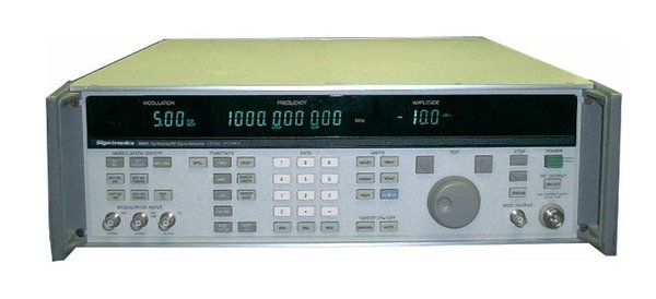
TBD — confirm which model(s) are owned: Check the front-panel model decal against (a) 6061A vs 6062A and (b) any “Fluke” branding (suggesting a pre-acquisition unit) vs “Giga-tronics” branding (post-acquisition, post-1995). Also confirm whether both units are rack-mounted as a pair, which would have been the typical ATE-bench configuration.
1.2 Spec sheet (the numbers that matter for radio work)
Pulled from the 6060A-series datasheet (02-inputs/manuals/gigatronics/Giga-tronics 6060A Series Datasheet.pdf):
Frequency accuracy and stability — same as the reference oscillator. The standard internal reference is a free-air 10 MHz crystal stable to <±10 × 10⁻⁶ across 0–50 °C with <±5 × 10⁻⁷/month aging and a 1-hour warm-up to within 1 ppm. Two oven-stabilized reference options exist: Option 132 (medium-stability oven, <±1 × 10⁻⁷ total across 0–50 °C, <±1 × 10⁻⁷/month aging, 20-minute warm-up to ±3 × 10⁻⁸) and Option 130 (high-stability oven, <±2 × 10⁻¹⁰/°C, <±5 × 10⁻¹⁰/day aging, 30-minute warm-up to ±1 × 10⁻⁸). For amateur receiver-alignment work, the standard crystal is sufficient — 1 ppm at 146 MHz is 146 Hz, well below any FM receiver’s IF bandwidth. For NIST-traceable lab work, the high-stability oven (Option 130) is the option to look for on the rear-panel option tag. TBD — confirm the unit’s reference-oscillator option by inspecting the rear-panel option sticker.
Spectral purity — harmonics:
Table 2 — Spectral purity — harmonics:
| Output level / freq | 6061A | 6062A |
|---|---|---|
| +13 to +16 dBm | N/A | −25 dBc |
| <+13 dBm, >100 kHz | −30 dBc | −30 dBc (>1 MHz) |
| <+13 dBm, 10–100 kHz | −26 dBc | −25 dBc (0.1–1 MHz) |
| Subharmonics, 1050–2100 MHz | N/A | −45 dBc |
Non-harmonic spurious: −55 dBc at 10–100 kHz; −60 dBc from 100 kHz to 1050 MHz (both models); −54 dBc from 1050–2100 MHz (6062A only). For receiver-IMD characterization at low input levels these are already 30–40 dB below the typical receiver’s IIP3 contribution, so the generator is not the limiting noise source for any reasonable test setup.
Residual FM (the spec that matters most for measuring narrow-band FM receivers): in a 0.5–3 kHz BW, ≤12 Hz rms below 245 MHz, ≤6 Hz rms in the 245–512 MHz range, ≤12 Hz rms in the 512–1050 MHz range, and ≤24 Hz rms above 1050 MHz (6062A). In the CCITT band, the numbers are roughly half (10/5/10/20 Hz rms). For aligning a typical scanner’s ±5 kHz NFM receiver, 12 Hz of residual FM is comfortably below the signal floor — the receiver’s own discriminator noise will dominate. For aligning a SSB receiver’s product detector, you’ll want the oven option, but a free-air crystal still produces a phase-noise floor that beats what most consumer radios can resolve.
Reverse power protection: the 6061A’s RF output absorbs up to 50 W of reverse RF from a 50 Ω source across 10 kHz–1050 MHz, plus up to 50 V DC. The 6062A is rated for 25 W reverse RF and 25 V DC. A flashing front-panel “RF OFF” annunciator lights when the reverse-power trip fires. The implication for bench practice: a 100 W transmitter (e.g., the XPA125B at full output) accidentally keyed into the 6062A’s RF output without a downstream attenuator/isolator will trip the protection but won’t kill the front end — but the margin is thin and a 1500 W amp will not be survived. Always insert a 20–30 dB attenuator + circulator between any TX-capable DUT and the signal generator’s output port.