Electrostatic CRT Tester — Mark 2 · Volume 7
Electrostatic CRT Tester — Vol 7: The Testable-Device Menagerie
Every glowing thing this box will light — scope and radar CRTs, dekatrons, Nixies, trigger tubes, magic eyes, the E1T, NIMO, and Geissler tubes — and exactly which knob feeds each one
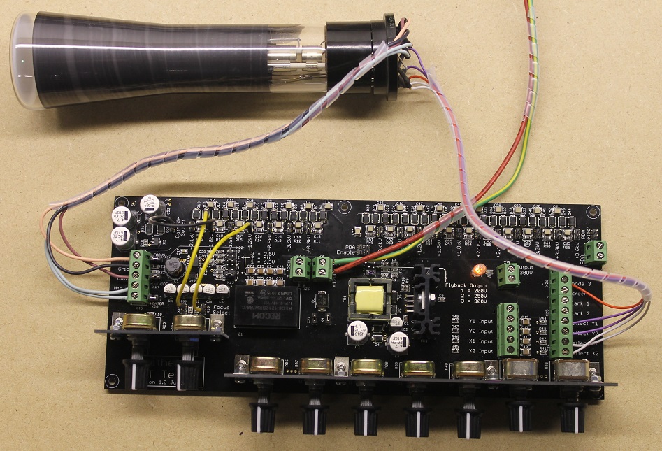
7.1 What this volume is for
The tester was built to bring an unknown electrostatic-deflection cathode ray tube to life (Vol 2 walks the electron from cathode to phosphor; Vol 6 is the safe bring-up order for a CRT). But the maker discovered — as everyone who builds an adjustable, isolated, multi-rail HV bench supply eventually does — that a box which can deliver a current-limited heater, an adjustable negative bias, and several hundred to several thousand volts of clean anode potential is a universal bench for an entire zoo of gas-discharge, beam-switching, and indicator devices. None of those devices has a dedicated tester any more; most never had one. The Mark 2 is the tester they never got.
This volume is the field guide to that zoo. It catalogues what the tester will light, groups the devices by how they are lit, gives a reference table for each family, and — for every class — names the exact tester output that feeds each electrode and the observable you are looking for. It closes with a master compatibility table you can pin to the bench.
The organising idea is simple. Everything here needs some combination of four things the Mark 2 supplies by hand:
- A heater (indirectly-heated cathode devices only — CRTs, magic eyes, E1T, NIMO).
- A negative control bias (CRT grid; magic-eye control grid).
- One or more positive anode/accelerator potentials, from a few hundred volts to ~5.6 kV.
- A current-limiting ballast so a gas device that strikes into a low-impedance arc does not run away.
Cold-cathode gas devices (dekatrons, Nixies, trigger tubes, bargraphs, Geissler tubes) skip the heater entirely — they only need items 3 and 4. That is why they are the easiest things on this list to light, and why they make a good confidence check that your EHT chain is healthy before you risk a real CRT.
Reading key for every “tester output” column below. The Mark 2’s rails, as specified: heater (≤ ~6 W: 6.3 V @ 0.6 A / 4 V @ 1.1 A / 2.5 V @ 2 A), grid bias g1 (−5 V to −120 V), focus anode (wide range), accelerating anode a2 (up to ~+2.2 kV), PDA (up to ~+5.6 kV), and the two push-pull deflection-plate pairs (−300 V to +300 V, AC-coupled X/Y + Z-mod inputs). When a device below is fed from “a2” or “PDA,” it means you are borrowing that rail — set to a much lower voltage than a CRT would use — as a general-purpose adjustable HV source, with an external series resistor as ballast. All electrode connections are 4 mm banana; external current and voltage meters clip on at the provided jacks.
7.2 Part 1 — Electrostatic cathode ray tubes
This is the tester’s home ground. The maker publishes an example list of tubes he has personally brought up on the Mark 2. Reproduced verbatim:
CV5125, 5SP7, SE5F, 6ЛO1И, 09D, 130BXB31, CV1522, D10/230, CV2175, 3ЛO1И, CV2272, DG7/32, CV2320, DG7/52A, ACR10, 7ЛO1М, 2BP1, DG7/5.
That list is a good cross-section of the whole electrostatic-CRT world: British commercial display tubes (the Mullard DG7 and D10 families), British/Commonwealth military CV (“Common Valve”) types, American JEDEC scope tubes (2BP1, 5SP7), and Soviet ЛO oscilloscope tubes. What they share is exactly what the tester is built for, and Part 1.3 explains why.
7.2.1 Decoding the type numbers
Half the battle with these tubes is reading the designation, because three or four different naming systems appear in one list. The tester does not care what a tube is called — it cares about the electrode voltages — but knowing the family tells you roughly what to expect before you clip on the first lead.
Table 1 — 1.1 Decoding the type numbers
| Naming system | Pattern | Worked example from the list | What it tells you |
|---|---|---|---|
| JEDEC (US) | (dia. in inches)(seq. letters)P(phosphor no.) | 2BP1 = 2-inch, 2nd registration, P1 green; 5SP7 = 5-inch, P7 long-persistence | Face size and phosphor directly |
| Mullard/British commercial | D/DG (dia. in cm) / (design no.) | DG7/32 = 7 cm, green (“G”), design 32; D10/230 = 10 cm | Face size in cm, “G” = green screen |
| British military “CV” | CV(sequential number) | CV1522, CV2175, CV2272, CV2320, CV5125 | Nothing on its face — must look up the CV register; many are re-badged commercial tubes |
| Soviet “ЛO” | (dia. in cm)ЛO(design)(phosphor letter) | 6ЛO1И = 6 cm, ЛO = осциллографическая (oscilloscope), phosphor “И”; 3ЛO1И = 3 cm; 7ЛO1М = 7 cm | Face size in cm; ЛO guarantees electrostatic scope tube |
Bench note — the Cyrillic ones are your friends. The Russian ЛO (“Л-О”, lampa oscillograficheskaya) suffix is a hard guarantee: it is an electrostatic-deflection, electrostatic-focus oscilloscope tube by definition, single gun, modest heater. If you see ЛO you can proceed without a datasheet — the leading number is the face diameter in centimetres (3, 6, 7 cm here), and the electrode order is the universal one from Vol 2. The 6ЛO1И and its siblings are some of the most tester-friendly tubes you will ever meet.
7.2.2 Reference table — the common types
The figures below are typical for each family, drawn from general electrostatic-CRT engineering practice and the common datasheets for these well-known tubes. Where a value genuinely varies between sub-types or is not reliably published for the exact device, the cell says so — do not treat these as datasheet-exact for your specific glass. The whole point of the tester (Vol 6) is that you bring the tube up empirically, watching the spot, precisely because you often cannot trust or find the numbers.
Table 2 — 1.2 Reference table — the common types
| Tube | Family / origin | Role | Face | Heater (typical) | Deflection | Phosphor (typ.) | Notes |
|---|---|---|---|---|---|---|---|
| DG7/32 | Mullard, British | Scope / indicator | ~7 cm round | ~6.3 V @ ~0.3 A | Electrostatic, both axes | Green (medium persist.) | The classic small British scope tube; huge installed base in valve-era ‘scopes and testers. Very tester-friendly. |
| DG7/5, DG7/52A | Mullard, British | Scope / indicator | ~7 cm round | ~6.3 V @ ~0.3 A | Electrostatic | Green | Sisters of the /32; minor gun/phosphor variations. “A” suffix = later production. |
| D10/230 | Mullard, British | Larger indicator | ~10 cm round | ~6.3 V (verify) | Electrostatic | Green | Bigger face → wants more accel/PDA for a bright, tight spot. |
| 2BP1 | RCA / JEDEC (US) | Small scope | 2-inch round | 6.3 V @ ~0.6 A | Electrostatic | P1 green | Tiny, cheap, forgiving; a good first tube on the tester. |
| 5SP7 | JEDEC (US) | Radar / scope | 5-inch round | 6.3 V (verify per sub-type) | Electrostatic | P7 blue-flash / long yellow persistence | P7 is the radar-PPI phosphor — a bright blue flash then a long yellow decay; do not mistake persistence for a stuck spot. Often a PDA tube. |
| SE5F | British (Mazda/other) | ~5-inch scope | ~5-inch | verify | Electrostatic | verify | Datasheet scarce — bring up empirically. |
| 09D, 130BXB31 | Mixed / obscure | Indicator | verify | verify | Electrostatic | verify | Uncommon designations; treat as fully unknown, follow Vol 6’s cautious ramp. |
| CV1522 / CV2175 / CV2272 / CV2320 / CV5125 | British military “CV” | Scope / radar / indicator | varies | varies (≤ ~6 W to fit) | Electrostatic | varies | CV numbers hide commercial equivalents; look up the CV register to recover the real type, then use its data. |
| 6ЛO1И / 3ЛO1И / 7ЛO1М | Soviet | Oscilloscope | 6 / 3 / 7 cm | modest (verify per type) | Electrostatic, both axes | green/blue per suffix | ЛO = guaranteed electrostatic scope tube; among the most predictable to bring up. |
Do not fabricate the heater number for your specific tube. The tester’s ~6 W ceiling is generous for every entry above, but the safe way to light an unknown heater is Vol 6’s method: start at the lowest plausible voltage, confirm the correct dull-orange cathode colour, and only raise it if the tube is clearly a higher-voltage heater. A DG7 heater glowing like a 12 V lamp means you have it wrong.
7.2.3 Phosphor quick-reference
The last character of a JEDEC number (and the maker’s own eye when he inspects a Soviet or CV tube) tells you the phosphor, and the phosphor sets both the colour you expect and how you interpret what you see. This matters directly on the tester: a long-persistence radar phosphor produces a lingering trail that a newcomer mistakes for a stuck or burned spot, and a short-persistence instrument phosphor gives you almost no help freezing a moving spot by eye. The types you will actually meet in the list above:
Table 3 — The last character of a JEDEC number (and the maker's own eye when he inspects a Soviet or CV tube) tells you the phosphor, and the phosphor sets both the colour you expect and how you interpret what you see. This matters directly on the tester: a long-persistence radar phosphor produces a lingering trail that a newcomer mistakes for a stuck or burned spot, and a short-persistence instrument phosphor gives you almost no help freezing a moving spot by eye. The types you will actually meet in the list above
| Phosphor | Colour (fluorescence) | Persistence | Typical role | On the tester you see |
|---|---|---|---|---|
| P1 | Yellow-green | Medium | General oscilloscope (2BP1) | A clean, quickly-following green spot — the “default” look |
| P7 | Blue flash → yellow decay | Long (cascade) | Radar PPI (5SP7) | A bright blue strike then a slow yellow trail — the trail is normal, not a fault |
| P31 | Green | Medium-short | Modern instrument | Bright, efficient green; easy to focus |
| P2 / P39 | Green | Long | Storage / slow-scan | Lingering green — again, persistence, not burn |
| Mullard “G” (DG7 etc.) | Green | Medium | British scope/indicator | The familiar valve-‘scope green |
Bench note — persistence vs. a burned spot. On a P7 (or any long-persistence) tube, park the spot and it leaves a glowing after-image that decays over seconds. That is the phosphor doing its job — do not crank the grid harder trying to “fix” a dim trail, and do not leave a bright stationary spot sitting on any phosphor for long (Vol 6): a genuinely burned spot is a permanent dark mark, and the way you create one is exactly by mistaking persistence for weakness and over-driving a parked beam.
7.2.4 CRT signature faults — reading the spot
The tester’s payoff is that a handful of visible symptoms sort an unknown CRT quickly. This table is the device-menagerie companion to Vol 6’s procedure — the same faults, indexed by what you see:
Table 4 — The tester's payoff is that a handful of visible symptoms sort an unknown CRT quickly. This table is the device-menagerie companion to Vol 6's procedure — the same faults, indexed by what you see
| What you see | Likely fault | Confirm with |
|---|---|---|
| Dim spot even at full grid drive / low a2 | Low emission — tired cathode | Compare cutoff bias vs. a known-good tube; emission falls with age |
| Blue haze filling the tube, soft/unfocusable spot | Gas (tube gone soft, lost vacuum) | The glow tracks beam current; a hard tube stays dark around the beam |
| No spot at all, heater lit | Open gun, no emission, or wrong anode polarity | Check heater colour, re-verify a2/PDA present at the jacks |
| No heater glow | Open heater | Ohm the heater cold; ∞ = open filament |
| Spot present but grid won’t blank it | Grid-cathode short or wrong bias reference | Meter g1–cathode; a short reads near 0 Ω |
| Spot smears / can’t reach sharp focus | Focus-anode range wrong, astigmatism, or gassy | Re-trim focus vs. a2; if it never sharpens, suspect gas |
| Spot deflects far more one axis than the other | Plate connection error or a shorted plate | Swap/verify the plate leads; meter each plate pair |
7.2.5 Why these tubes all suit the Mark 2
Every tube in the list obeys four constraints, and those four constraints are the tester’s entire design envelope:
- Electrostatic deflection. The beam is bent by voltage on plate pairs, not by a yoke’s magnetic field. The Mark 2 supplies ±300 V push-pull to two orthogonal plate pairs (Vol 2 §deflection). A magnetic-deflection tube has no plates to drive and would sit dead on this bench.
- Electrostatic focus. The gun focuses with an einzel (unipotential) lens set by the focus-anode voltage — a knob on the Mark 2 — not with a focus coil. No magnetic focus hardware is needed or supported.
- Single gun, modest heater. One electron gun drawing a heater that fits under ~6 W. Every tube above is a single-gun scope/indicator type; none is a colour or multi-beam tube.
- Anode/PDA within the ceiling. Accelerator ≤ ~2.2 kV and PDA ≤ ~5.6 kV covers small scope and radar CRTs comfortably. The 2-inch and small green tubes barely tax it; the 5-inch radar tubes (5SP7) use the PDA rail as intended (Vol 2 explains why a PDA tube wants a high final anode after the plates so deflection sensitivity survives).
        THE MARK 2 VOLTAGE LADDER  (where a CRT sits)
  +5.6 kV ─┬─  PDA (helix, post-deflection)  ── 5SP7 & other PDA tubes
           │
  +2.2 kV ─┼─  a2 accelerating anode         ── every CRT's beam energy
           │
  focus  ──┼─  focus anode (einzel lens)      ── set for a tight spot
           │
     0 V ──┼─  cathode reference
           │
   −5 V ───┼─  g1 grid, near cutoff
           │
  −120 V ──┴─  g1 grid, full blank / high-a2 cutoff
     ±300 V across each deflection-plate pair (push-pull), AC-coupled X/Y + Z-mod
7.2.6 What the tester will NOT test — the exclusions
The same four constraints define the tubes that are out of scope. This matters: clipping a magnetic-deflection TV tube onto the deflection jacks will do nothing useful and can waste a lot of bench time chasing a “dead” tube that was never a candidate.
Table 5 — 1.6 What the tester will NOT test — the exclusions
| Excluded class | Why it fails on the Mark 2 | Example |
|---|---|---|
| Magnetic-deflection tubes | Beam is steered by a yoke, not plates — nothing for ±300 V to bend | Any TV picture tube, most large radar PPIs |
| Magnetic-focus tubes | Focus is a coil, not the focus-anode voltage | Some large display/TV CRTs |
| Multi-gun tubes | Only one gun can be run at a time; no simultaneous drive | Colour CRTs, dual-beam scope tubes |
| Heaters > ~6 W | Exceeds the heater rail (cannot do 6.3 V @ 1.2 A) | Large TV/display tubes with fat cathodes |
| PDA requirement > ~5.6 kV | Above the EHT ceiling — will show a dim spot at best | Some large/bright display CRTs |
| Trace-rotation coils | The Mark 2 has no rotation-coil drive | Precision instrument CRTs with a rotation yoke |
A partial candidate — a tube that is electrostatic-deflection and single-gun but wants, say, 6 kV PDA — will still light: you will get a spot, just not at full brightness or full performance. The maker notes exactly this: a tube needing >5 kV PDA “may still show a spot but at reduced performance.” That is often good enough to sort a tube good/weak/dead even when it is not good enough to characterise it fully.
7.3 Part 2 — Cold-cathode neon (gas-discharge) devices
No heater, no focus, no deflection — these devices work on one principle: apply enough voltage across a gas-filled gap and it strikes into a glow discharge, then maintains the glow at a lower voltage. The Mark 2’s role is to be the adjustable, current-limited HV source that strikes them and holds them without letting the discharge run away into a destructive arc. This is the family where the tester doubles as a general neon-tube power supply, and it is the material that overlaps directly with the Electronics — Neon Ring Counters project, which lives and breathes cold-cathode glow-transfer counting.
The universal cold-cathode drive is the same for all of them:
        COLD-CATHODE NEON DRIVE  (tester as adjustable HV + ballast)

   tester anode rail ──[ R_ballast ]──●── ANODE of device
   (a2 set low, e.g.                  │
    +150…+500 V)                      ▽  gas gap glows when V > V_strike
                                      │
   selected CATHODE ─────────────────●──→ to 0 V (or via meter)
                                      │
   ( for trigger tubes: a 3rd lead — the TRIGGER/starter — taps a
     small pulse or bias from the grid/bias rail to fire the gap )

   R_ballast sets the glow current: I = (V_anode − V_maintain) / R_ballast
Raise the anode rail from zero. Nothing happens until you cross the strike (ignition) voltage, at which point the gap lights abruptly. Now the gap’s voltage drops to the maintaining voltage and the ballast resistor absorbs the difference, fixing the current. Back the anode down and the glow persists — with hysteresis — until you fall below maintaining, where it extinguishes. Watching that strike/extinguish hysteresis on a meter is itself a health check: a gassy or worn tube strikes high, maintains erratically, or flickers.
Bench note — always ballast a gas device. A cold-cathode gap is a negative-resistance load once struck: give it a stiff voltage source with no series resistor and the current climbs until something melts. Every device in Part 2 is fed through a series ballast resistor sized for its rated glow current (typically a few hundred µA to a few mA). The tester’s provision for an external current meter is exactly how you confirm you are in the right current window.
7.3.1 Dekatrons — counting and dividing glow-transfer tubes
A dekatron (GC10B, OG-series, Z504S, and many others) is a cold-cathode ring counter in a single envelope: a central disc anode surrounded by ten main cathodes, with one or two sets of guide (transfer) cathodes interleaved between them. A glow sits on one main cathode. Pulse the guides in sequence and the glow transfers to the next main cathode — the tube counts in base ten, visibly, one glowing dot walking around a ring. Chain them and each tube divides by ten. This is the direct ancestor of the neon ring-counter circuits covered in the Electronics — Neon Ring Counters dive, and the tester is the ideal bench for exercising a single tube before you commit it to a counter string.
On the Mark 2: the anode disc goes to a low-set a2 rail (a few hundred volts) through the anode ballast resistor; each main cathode returns to 0 V (via the current meter to read glow current). To see it count rather than just glow, you feed the guide electrodes a two-phase (or single-phase, for a single-guide type) pulse train from an external generator referenced to the tester’s rails — the tester holds the DC operating point steady while your pulses do the stepping. What you observe: a clean, single bright glow that transfers crisply one step per pulse, with no split glow, no back-transfer, and no dim/reluctant positions (a worn cathode shows as a dim or sticky count position).
7.3.2 Nixie tubes — the ZM1040
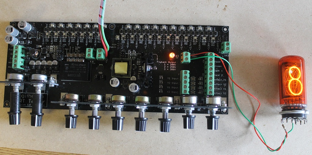
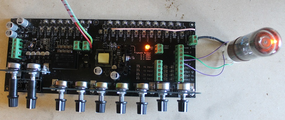
A Nixie is the display-only cousin of the dekatron: ten cathodes shaped as the numerals 0–9 stacked inside a common wire-mesh anode, in neon. Whichever cathode you connect to the return glows in that familiar orange, silhouetting its digit. The ZM1040 is a large Philips end-view Nixie — a good, bright, robust tube to demonstrate on.
On the Mark 2: the anode takes the low-set HV rail through the anode resistor (which sets digit-current, typically a couple of mA); the ten cathodes are individually switchable to the return. Raise the rail until the selected digit strikes (a Nixie’s ignition is typically ~170 V, maintaining ~140 V — verify per type), then trim the ballast for an even, flicker-free glow that covers the whole numeral without “haloing” onto neighbours. Stepping through 0–9 by moving the cathode lead confirms every cathode fires and that none has gone lazy from cathode poisoning (a classic Nixie fault where an under-used digit strikes dim and blotchy). This is a display, not a counter — there are no guide electrodes to step — so the tester’s job is purely to strike and hold at the right current.
7.3.3 Trigger tubes — the Z700U
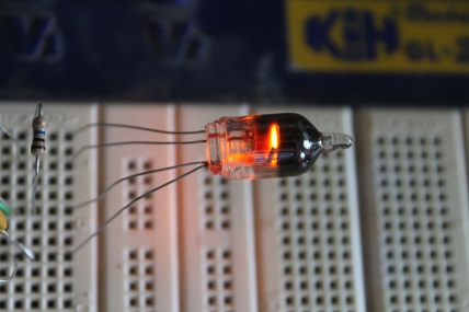
A trigger tube (the Z700U is a classic cold-cathode example) is a gas gap with a third trigger (starter) electrode. You hold the main anode below its self-ignition voltage, so it sits dark; a small pulse or bias on the trigger electrode ionises the gas locally and fires the main gap. It is the cold-cathode analogue of a thyratron: a gas-discharge switch with a control terminal, used historically in relay drivers, ring counters, and timing circuits.
On the Mark 2: the anode sits on a sub-ignition HV rail through its ballast; the cathode returns to 0 V; the trigger is fed from the bias/grid rail (or a small external pulse) so you can watch the gap fire and hold. What you observe: the main gap stays dark below the trigger threshold, fires cleanly when the trigger is applied, and maintains on its own afterward (a true trigger tube latches on until the anode is starved below maintaining — like a gas SCR). A tube that self-strikes with no trigger, or refuses to fire even with full trigger drive, is telling you it is out of spec. The negative-bias and adjustable-anode capability that the tester already has for CRT grids is exactly what a trigger tube’s three-terminal behaviour needs.
7.3.4 Bargraph indicators and other neon types — GTE175M
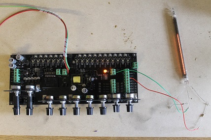
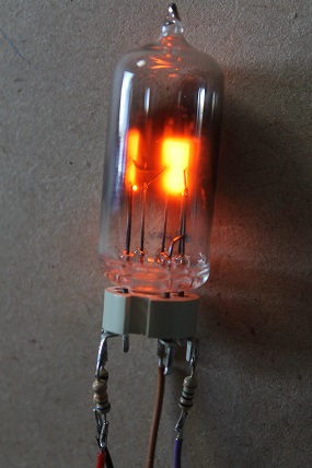
The cold-cathode family has a long tail of indicators — neon bargraph displays (columns of individually-struck cells, or self-scan plasma bars, whose lit length shows an analogue quantity) and single- or multi-segment neon indicator devices such as the GTE175M. Electrically they are all the same animal as the Nixie: one or more cathodes inside an anode in neon, struck above ignition and held on maintaining through a ballast. The tester lights each cell/segment so you can confirm strike voltage, even glow, and the absence of dead cells. For a bargraph, walking the drive up and down shows the bar grow and shrink; for a simple indicator like the GTE175M, you are confirming clean ignition and a steady, full-area glow.
7.3.5 Cold-cathode summary table
Table 6 — 2.5 Cold-cathode summary table
| Device (example) | Class | Strike / maintain regime (typical) | Tester output that drives it | What you observe / test for |
|---|---|---|---|---|
| Dekatron (GC10B, Z504S) | Glow-transfer counter | Anode a few hundred V; guides pulsed | a2 set low + ballast → anode; guides from ext. pulse gen; cathodes → meter | Single crisp glow that steps one position per pulse; no split/back-transfer; no dim positions |
| Nixie ZM1040 | 10-cathode display | Strike ~170 V, maintain ~140 V (verify) | a2 low + anode resistor; cathodes switched to return | Every 0–9 digit strikes bright and even; no cathode poisoning / haloing |
| Trigger tube Z700U | 3-electrode gas switch | Anode below self-strike; trigger fires it | a2 low + ballast → anode; bias rail (or pulse) → trigger; cathode → return | Dark until triggered, fires cleanly, latches on; correct threshold |
| Neon bargraph | Analogue bar indicator | Per-cell strike; drive-dependent length | a2 low + ballast; drive walked up/down | Bar length tracks drive; no dead cells |
| GTE175M / general neon indicator | Neon indicator | Strike above ignition, hold on maintain | a2 low + ballast → anode; cathode → return | Clean ignition, steady full-area glow |
Cross-project — Neon Ring Counters. The dekatron and trigger-tube material here is the device-level view; the Electronics — Neon Ring Counters dive is the circuit-level view — how you chain these into a working glow-transfer counter, the HV supplies, the guide-pulse timing, burn-in and drift. Bring a suspect tube up on the Mark 2 first, confirm it is healthy, then commit it to a counter string. The tester is the incoming-inspection bench for that whole project’s parts bin.
7.4 Part 3 — Magic-eye / tuning-indicator valves
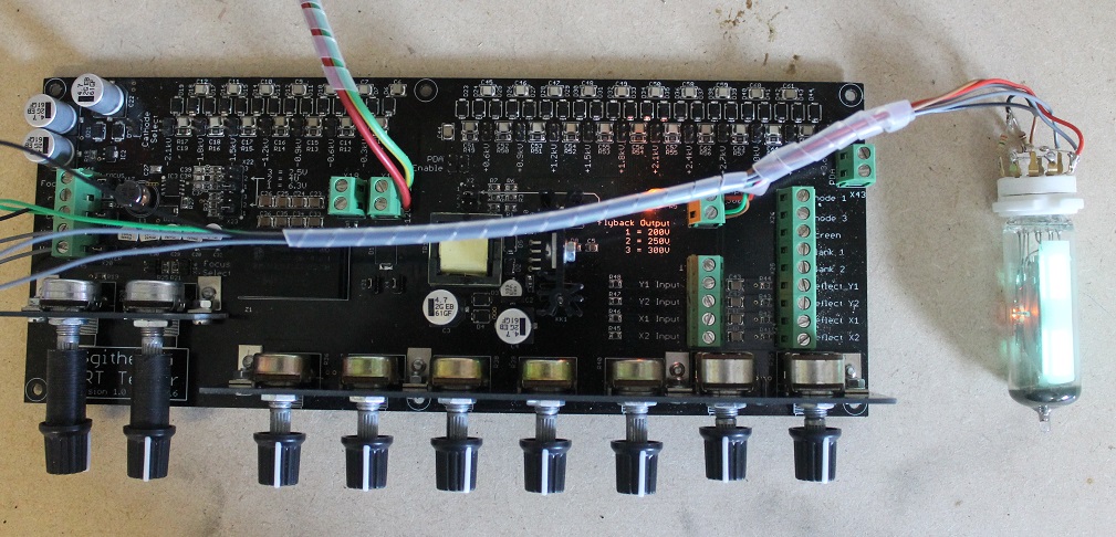
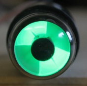
A magic eye is a miniature CRT with none of the deflection machinery: an indirectly-heated cathode, a fluorescent-coated target anode at a few hundred volts, and a ray-control electrode that casts a shadow across the target. As the control voltage swings, the shadow opens and closes — the “eye” that shows radio-tuning peak or tape-recording level in valve-era gear. The EM87 is a bar/ribbon-type indicator (a horizontal glowing bar that shortens with signal); the 6AF6G is the American dual-pattern type with two target sectors and two ray-control electrodes.
Because it is a little CRT, the magic eye maps neatly onto the tester’s rails:
Table 7 — Because it is a little CRT, the magic eye maps neatly onto the tester's rails
| Electrode | EM87 role | 6AF6G role | Fed from (Mark 2) |
|---|---|---|---|
| Heater | Indirect cathode heat | Same | Heater rail (6.3 V — well under the ~6 W limit) |
| Target / anode | Fluorescent screen at ~+250 V | Two target sectors at ~+250 V | a2 rail set low (~+200…+300 V) through an anode resistor |
| Ray-control / deflection electrode | Casts the shadow; its voltage sets bar length | Two ray electrodes | a2-derived tap or the deflection rail, varied to open/close the shadow |
| Control grid (driver, where present) | Drives the ray electrode in service | — (6AF6G needs an external driver) | Grid-bias rail (−5…−120 V) as the “signal” input |
On the Mark 2 you light the heater, set the target to a couple of hundred volts through a resistor, and vary the control/grid voltage to sweep the shadow open and shut. What you are grading: target brightness (a tired magic eye is dim — this is the classic “the eye is worn out” fault, since the fluorescent target ages faster than the cathode) and shadow travel (does the bar/pattern go fully open and fully closed over the control range?). A bright, full-travel eye is good; a dim one that will not close is spent. Note the 6AF6G is only the indicator — in a real set a triode drives its ray electrode — so on the tester you supply that control voltage yourself from the bias rail.
Cross-project — Television. Magic-eye valves and the small green display CRTs in Part 1 are close kin to the display devices in the Television project’s mechanical- and electrostatic-display work: all are cathodoluminescent — an electron beam exciting a phosphor — differing only in whether the beam is deflected (CRT), shadowed (magic eye), or mechanically scanned. The Mark 2 is the common bench that lights any of them.
7.5 Part 4 — The E1T beam-switching decade counter tube
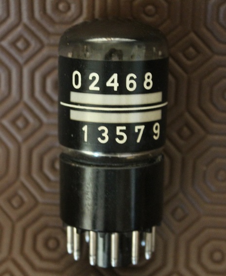
The E1T is one of the most exotic things the tester will run, and it is exotic precisely because it sits halfway between a CRT and a counter. It is a beam-switching (beam-deflection) decade counter valve from Philips: a hot cathode forms a flat, ribbon-shaped electron beam; a pair of deflection plates steers that beam electrostatically across an aperture plate with ten positions; and a feedback electrode locks the beam onto whichever of the ten it is nearest, so each input pulse deflects the beam by exactly one position. It counts to ten, resets, and carries — and, because a small phosphor/target shows where the beam lands, it displays its count as a glowing position. It is a genuine electrostatic-deflection device, which is why the CRT tester exercises it so naturally.
Why it is exotic: it is a single-envelope digital decade counter built entirely from an electron beam and deflection plates, made in a narrow window in the 1950s before transistors made it obsolete. Working E1Ts are prized, and few benches can drive one properly — but the Mark 2 has every rail it needs.
Table 8 — Part 4 — The E1T beam-switching decade counter tube
| E1T electrode | Function | Fed from (Mark 2) |
|---|---|---|
| Heater | Indirect cathode heat | Heater rail (6.3 V) |
| Cathode / beam-forming | Emits and shapes the ribbon beam | Cathode reference (0 V) |
| Deflection plates | Steer the beam across the 10 targets | Deflection rail (±300 V push-pull) and/or external step pulses |
| Anode / target | Collects the beam; the lit position shows the count | a2 rail set to the E1T’s modest anode voltage |
| Reset / feedback electrodes | Lock the beam to a step; reset to zero | Bias / auxiliary rails |
On the tester you bring the heater up, set the anode to its (modest, few-hundred-volt) operating point, and use the deflection rail — the very same push-pull ±300 V that bends a CRT’s spot — to walk the beam across the ten positions. Static, you can confirm the tube forms a clean beam and lands on a defined position; to make it count you feed step pulses to the deflection input from an external generator, exactly as with the dekatron guides. It is the fastest of the decade counters here (it was built for kHz counting where a dekatron could not keep up), and seeing one step through ten on the bench is a genuine treat.
7.6 Part 5 — NIMO tubes
There is no dedicated assigned photo for the NIMO here, but it belongs squarely in this menagerie because of how it is tested: a NIMO is a small CRT. Made by IEE (Industrial Electronic Engineers), a NIMO tube (the BA-series, e.g. the single-digit types) is a cathode-ray display in which an electron gun’s beam is shaped by a stencil mask carrying the ten numeral outlines; selecting a digit routes the beam through that stencil so the numeral is projected and accelerated onto a small phosphor screen — a crisp, bright, sharp-edged digit with none of a Nixie’s stacked-cathode depth.
Because it is a CRT, it is tested as one:
Table 9 — Because it is a CRT, it is tested as one
| NIMO electrode | Function | Fed from (Mark 2) |
|---|---|---|
| Heater | Indirect cathode heat | Heater rail (6.3 V) |
| Cathode / grid | Emits and gates the beam | Cathode ref + grid-bias rail (−5…−120 V) for brightness/blanking |
| Digit-select / stencil electrodes | Choose which numeral the beam forms | Switched from an anode/bias rail per the tube’s selection scheme |
| Accelerator / anode | Accelerates the shaped beam to the screen | a2 rail (NIMO wants a healthy accelerating voltage — hundreds of volts to low kV) |
| Phosphor screen | Displays the numeral | (collected via final anode / aquadag) |
On the Mark 2 you light the heater, set the grid bias for a bright-but-not-blooming digit, bring the accelerator up on the a2 rail until the numeral is sharp, and step the digit-select electrodes to confirm all ten numerals form cleanly and focus evenly. Everything you learned bringing up a real CRT in Vol 6 applies directly — the NIMO is, for the tester’s purposes, just a very small, very specialised display CRT. Faults read the same way: dim = low emission or low accelerator; fuzzy = wrong focus/accelerator balance; missing segments of a digit = a stencil/selection problem.
7.7 Part 6 — Geissler tubes
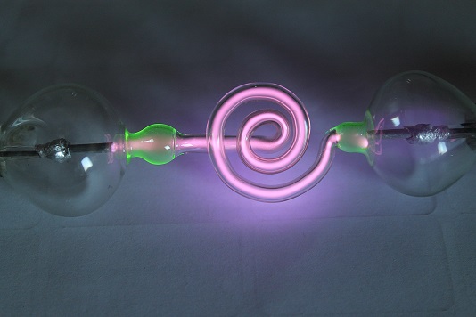
A Geissler tube is the oldest device in the zoo — a sealed glass tube with a low-pressure gas fill and an electrode at each end, the 19th-century demonstration piece that showed gas discharge glows. Strike it with a few kilovolts and the rarefied gas fluoresces along its length, the colour set by the fill (neon = red-orange, mercury vapour = blue, and so on) and often enhanced by fluorescent glass or internal phosphor. It is pure gas-discharge novelty — no gun, no counting, no display function — and the only thing it needs is high voltage.
Here the tester is at its simplest: it is a variable HV source. The EHT rails (a2 up to ~2.2 kV, PDA up to ~5.6 kV) drive the two electrodes through a ballast, and you wind the voltage up until the tube strikes. Because the Mark 2’s EHT is adjustable, you can find the exact strike voltage, then back it off to a steady, pretty glow just above the maintaining point — which is far kinder to an antique tube than slamming it with a fixed high-voltage supply. A ballast resistor is essential (Part 2’s rule applies: a struck gas column is a negative-resistance load). What you are confirming: the tube still holds vacuum and strikes at a reasonable voltage — a tube that will not strike at all, or strikes then goes dark, has lost its gas fill or cracked its seal.
Safety — EHT is lethal, and Geissler tubes tempt you to linger. Everything in Parts 2 and 6 runs on the tester’s high-voltage rails, up to ~5.6 kV. The one-hand rule applies (Vol 6 /
_shared/legal_ethics.md): bleed every HV node before touching anything, use EHT-rated leads, keep the other hand in a pocket, and remember the AC-coupling caps and EHT multiplier hold their charge after you switch off. A pretty Geissler glow is exactly the situation where people relax and reach in with two hands — do not.
7.8 Part 7 — Master compatibility table
Pin this to the bench. It collapses the whole menagerie into one view: what the tester supplies to each device class, whether it is a clean fit, and the caveat that bites.
Table 10 — Part 7 — Master compatibility table
| Device class | Testable? | Heater | Neg. bias | Anode / accel | PDA (>2 kV) | Deflection plates | Ballast needed | Key caveat |
|---|---|---|---|---|---|---|---|---|
| Electrostatic scope/indicator CRT (DG7, D10, 2BP1, CV, ЛO) | ✅ Yes — home ground | ✅ 6.3 V etc. | ✅ g1 −5…−120 V | ✅ a2 ≤ 2.2 kV | ✅ up to 5.6 kV | ✅ ±300 V X & Y | No | Bring up empirically (Vol 6); heater ≤ ~6 W |
| 5-inch radar CRT (5SP7, P7) | ✅ Yes | ✅ | ✅ | ✅ | ✅ (uses PDA) | ✅ | No | P7 long persistence ≠ stuck spot; wants PDA |
| Magnetic-deflection / -focus tube | ❌ No | — | — | — | — | ❌ no yoke drive | — | Out of scope — no coil drive |
| Multi-gun / colour CRT | ⚠️ One gun only | ✅ | ✅ | ✅ | ✅ | ✅ | No | Cannot run guns simultaneously |
| CRT needing >5 kV PDA | ⚠️ Partial | ✅ | ✅ | ✅ | ⚠️ ceiling | ✅ | No | Dim spot at best; enough to sort good/dead |
| Dekatron (glow-transfer counter) | ✅ Yes | — | — | ✅ a2 low (few hundred V) | — | (guides via ext. pulse) | ✅ Yes | Needs external guide-pulse gen to count |
| Nixie (ZM1040) | ✅ Yes | — | — | ✅ a2 low, strike ~170 V | — | — | ✅ Yes | Watch for cathode poisoning |
| Trigger tube (Z700U) | ✅ Yes | — | ✅ trigger from bias rail | ✅ a2 below self-strike | — | — | ✅ Yes | Latches on until anode starved |
| Neon bargraph / indicator (GTE175M) | ✅ Yes | — | — | ✅ a2 low | — | — | ✅ Yes | Check for dead cells / even glow |
| Magic-eye valve (EM87, 6AF6G) | ✅ Yes | ✅ 6.3 V | ✅ grid as “signal” | ✅ target ~+250 V | — | (control electrode) | (anode resistor) | Grade target brightness + shadow travel; 6AF6G needs you to supply drive |
| E1T beam-switching counter | ✅ Yes | ✅ | ✅ aux | ✅ a2 modest | — | ✅ ±300 V steers beam | (anode resistor) | Ext. step pulses to count; prized/rare |
| NIMO (CRT digit display) | ✅ Yes — it is a CRT | ✅ | ✅ grid | ✅ a2 accel | possibly | (stencil select) | (anode resistor) | Test exactly like a small CRT |
| Geissler tube | ✅ Yes | — | — | ✅ EHT as variable HV | ✅ up to 5.6 kV | — | ✅ Yes | Just needs adjustable HV; find strike then back off |
Legend: ✅ full fit · ⚠️ partial/with a caveat · ❌ out of scope · — not applicable to that device.
7.9 Where this leaves you
The through-line of the whole menagerie is that a hand-adjustable, isolated, current-limited, multi-rail HV supply is a more general instrument than its name suggests. Built to bring up an electrostatic CRT, the Mark 2 turns out to be the natural bench for anything that runs on a heater, a bias, and a few hundred to a few thousand volts of clean anode potential — which is to say, most of the beautiful glowing tubes the valve era produced and never gave a proper tester. Vol 2 is the physics behind the CRTs; Vol 6 is the safe procedure that gets any of these devices lit; the Neon Ring Counters and Television projects are where the counting tubes and display tubes go on to do real work. This volume is the map of everything the box will light on the way there.
Comments (0)