Electrostatic CRT Tester — Mark 2 · Volume 2
Electrostatic CRT Tester — Vol 2: How an Electrostatic CRT Works
Follow one electron from a hot cathode to a glowing spot — and watch which tester knob owns each step of the trip
2.1 Why this volume exists
The Electrostatic CRT Tester — Mark 2 does exactly one thing, but it does it to a device that needs a fistful of different voltages all present at once and all in the right relationship. To use the tester intelligently — to know why the spot won’t sharpen, why the trace is dim at full drive, why one axis deflects twice as far per volt as the other — you have to know what each electrode inside the tube is doing and which front-panel supply reaches into the neck to drive it.
This volume walks the electron from the moment it boils off the cathode to the moment it slams into the phosphor, and at every electrode it names three things: the electrode’s role, the tester supply that feeds it, and the typical value you set. Vol 4 is where the tester’s own circuitry gets dissected — how the flyback generates the EHT, how the −5…−120 V grid rail is derived, how the ±300 V push-pull deflection amplifiers work. Here we stay inside the glass and treat each tester supply as a labelled knob. Vol 6 then puts it together into a cold-start bring-up procedure. Read this one for the physics; read those two for the wiring and the ritual.
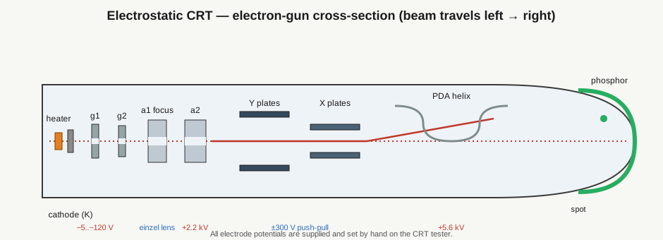
The lead figure above is the map for the whole volume. Keep referring back to it — the sections below march left to right across it, electrode by electrode.
2.2 The master electrode table
Here is the whole trip on one page. Every row is one electrode (or electrode group); every row names the tester supply that drives it and the value you would typically dial for a small round-face scope or radar CRT such as a DG7/32, 2BP1, or 5SP7. Treat this as the index for the rest of the volume — each electrode gets its own section below.
Table 1 — The master electrode table
| # | Electrode | Role in the tube | Tester supply that drives it | Typical value |
|---|---|---|---|---|
| 1 | Heater (f) | Warms the cathode indirectly; no beam role itself | Current-limited heater rail (~6 W) | 6.3 V @ 0.6 A / 4 V @ 1.1 A / 2.5 V @ 2 A |
| 2 | Cathode (K) | Thermionic electron source; defines 0 V reference for the gun | Ground / cathode-return (bias measured relative to it) | 0 V (reference) |
| 3 | Control grid g1 (Wehnelt) | Negative bias throttles beam current → brightness; also the Z-axis / blanking input | Grid-bias rail, −5…−120 V | −20…−70 V (cutoff typically −30…−90 V) |
| 4 | Accel/screen grid g2 | First accelerating aperture; sets the beam-forming crossover with g1 | Fixed or lightly-adjustable positive tap off the accel rail | +250…+600 V |
| 5 | Focus anode a1 | Centre element of the einzel lens; its voltage focuses the spot | Wide-range focus supply | Broadly adjustable; often 20–35 % of a2 |
| 6 | Accelerating anode a2 | Final gun anode; sets beam energy entering the deflection region | Accel EHT (flyback-derived), ≤ +2.2 kV | +1.0…+2.2 kV |
| 7 | Y deflection plates | Vertical deflection (differential/push-pull) | ±300 V push-pull deflection, AC-coupled Y input | −300…+300 V differential |
| 8 | X deflection plates | Horizontal deflection (differential/push-pull) | ±300 V push-pull deflection, AC-coupled X input | −300…+300 V differential |
| 9 | PDA helix (post-deflection anode) | Adds beam energy after the plates → brightness without losing deflection | PDA EHT (flyback-derived), ≤ +5.6 kV | +3…+5.6 kV |
| 10 | Aluminised phosphor + aquadag | Converts beam energy to light; aquadag = final anode, collects secondaries | Tied to the final anode (PDA on PDA tubes, else a2) | at final-anode potential |
⚠ Every one of those potentials is live at once. A working CRT under test simultaneously carries a hot heater, a −120 V grid, a +2.2 kV accel anode, a +5.6 kV PDA, and ±300 V on the plates. The accel and PDA nodes are lethal EHT, and the AC-coupling capacitors on the X/Y inputs plus the EHT multiplier stack hold their charge after power-down. One-hand rule above ~50 V; bleed every HV node before you reach into the neck. Full safety treatment is in Vol 8.
2.3 Cathode and heater — where the electrons come from
Everything downstream is just steering and accelerating a supply of free electrons that originates here. Get this stage wrong and no amount of correct voltage anywhere else produces a usable spot.
2.3.1 Indirectly-heated oxide cathode
Almost every electrostatic CRT you will meet uses an indirectly-heated oxide-coated cathode: a small nickel cylinder (the cathode proper, electrode K) coated on its end-cap with a mix of barium/strontium/calcium oxides, with an electrically-separate tungsten heater filament threaded up inside it and insulated from it. The heater’s only job is thermal — it brings the cathode to roughly 700–850 °C so the oxide coating emits electrons by thermionic emission. Because the heater is a separate element, the emitting surface can sit at a defined potential (the cathode potential, which the tester treats as the 0 V reference for the whole gun) independent of the heater supply. That is why the tester’s heater rail is a floating, current-limited winding and not referenced to the grid or anode rails.
The Richardson–Dushman relation governs how hard the surface emits:
J = A·T² · e^(−W/kT)
where J is the saturated emission current density, T the absolute cathode temperature, W the work function of the oxide coating, and A a material constant. The exponential in T is the whole story: a cathode run 10 % cool emits dramatically less, and an aged cathode whose coating has partially poisoned (raised W) is permanently down on emission no matter how you drive the heater. This is what “tired tube” means in practice.
2.3.2 Space charge, and why warm-up matters
At the operating temperature the cathode emits far more electrons than the beam actually draws. The surplus forms a negative space-charge cloud just off the cathode face — a virtual reservoir the gun dips into. In normal operation the CRT runs space-charge-limited, not emission-limited: the g1 bias, not the raw emission, decides how much current the beam carries, and that is what makes brightness controllable and stable. A healthy cathode always has cloud to spare.
Warm-up matters for two reasons. First, the coating must reach temperature before the cloud exists — rush the accel anode up before the cathode is hot and you draw beam current from a bare, under-emitting surface, which can strip coating (cathode “stripping”). Second, oxide cathodes like a gentle ramp; slamming full heater volts onto a cold filament thermally shocks it. The bring-up sequence in Vol 6 always brings the heater up first and lets it stabilise for tens of seconds before any anode voltage is applied.
Table 2 — Space charge, and why warm-up matters
| Heater option (≤ 6 W tester limit) | Rail setting | Draw | Typical tube family |
|---|---|---|---|
| 6.3 V heaters | 6.3 V | 0.6 A | Most Western scope/radar CRTs (DG7/32, 2BP1, 5SP7) |
| 4 V heaters | 4 V | 1.1 A | Older European / some indicator tubes |
| 2.5 V heaters | 2.5 V | 2.0 A | Early / low-voltage-heater types |
⚠ The tester’s heater is capped at ~6 W. It cannot run a 6.3 V @ 1.2 A heater — a big or twin-cathode tube will simply never reach emission temperature and will read as low-emission even when perfectly good. Check the heater rating against the 6 W envelope before you conclude a tube is dead. This limit is a design constraint of the tester (Vol 4), not a fault in the tube.
Low emission is the classic old-CRT fault. Symptom on the tester: the spot is dim even with g1 driven right up toward 0 V (maximum brightness demand) and the accel/PDA at full. A good cathode makes a bright spot with grid bias still well negative; a tired one needs the grid almost at cathode potential just to get a faint glow, and even then it can’t be driven bright. Because the tester lets you set the grid bias and the anode voltages independently and read them on external meters, you can quantify this rather than eyeball it — see the closing measurement table.
2.4 Control grid g1 — the Wehnelt, and cutoff
The first thing the emitted electrons meet is the control grid, g1, historically the Wehnelt cylinder: a metal cap surrounding the cathode with a small central aperture the beam passes through. In the lead figure it is the short element immediately right of the cathode, driven by the tester’s −5…−120 V grid-bias rail.
2.4.1 Negative bias throttles the beam
g1 sits negative with respect to the cathode. That negative field opposes the electrons trying to leave the space-charge cloud, and only the ones with enough forward energy squeeze through the aperture. Make g1 more negative → fewer electrons pass → dimmer spot. Make g1 less negative (closer to cathode potential) → more beam current → brighter spot. This is the brightness control, and unlike a rheostat dimming a lamp it works by modulating the beam current at the source, which is exactly why the same electrode doubles as the fast Z-axis / blanking / modulation input.
On the Mark 2 the DC grid bias is set by a pot on the −5…−120 V rail, and there is a separate AC-coupled grid-modulation (Z) input so an external signal can brighten and dim the spot on top of the DC bias — for intensity-modulating a trace, or for blanking. Vol 4 covers how those two are summed onto g1.
2.4.2 Cutoff bias — the number that matters
Push g1 negative enough and the field completely pinches off the beam: no electrons reach the anode, the spot goes black. The grid voltage at which the beam just extinguishes (at a given g2/a2 accelerating voltage) is the cutoff bias, and it is one of the most useful single numbers the tester measures. Cutoff is not a fixed property of the tube alone — it scales with the accelerating voltage, because a higher g2/a2 pulls harder on the electrons and takes a more negative grid to hold them back.
Table 3 — Cutoff bias — the number that matters
| What you read | How the tester lets you get it | What it tells you |
|---|---|---|
| Cutoff bias V₋co | With accel/PDA set, make g1 more negative until the spot just disappears; read the grid voltmeter | Gun health + where the usable brightness range sits |
| Usable grid swing | Cutoff bias minus the bias that gives full bright | The dynamic range available to the Z-axis input |
| Cutoff vs accel voltage | Repeat cutoff reading at two a2 settings | Confirms the cutoff-scales-with-accel behaviour; a flat or erratic result flags a gassy/leaky gun |
A typical small scope CRT might cut off around −30 to −90 V depending on how hard you have the accel and screen running. Two diagnostic tells: a cutoff that is way less negative than expected (spot blanks at only a few volts of bias) points at low emission — there just isn’t much beam to hold back; a cutoff that won’t hold (spot glows faintly no matter how negative g1 goes, or the whole tube shows a soft blue haze) points at gas — ionised residual gas inside a soft tube neutralises the grid field. Gas also shows as soft, un-sharpenable focus, covered next.
The tester’s −5…−120 V range is deliberately wide so it can find cutoff on tubes that run their accelerator anywhere from a few hundred volts to the full +2.2 kV. If you can’t reach cutoff at the negative end of the pot, your accel voltage is probably set higher than that tube needs — back off a2 and try again rather than assuming the grid is faulty.
2.5 Focus — the einzel (unipotential) lens
Emitting a controllable stream of electrons is only half the gun’s job. The beam leaving g1 is diverging — it has to be brought to a point on the screen, tens of centimetres away. Electrostatic CRTs do this with an einzel lens (also called a unipotential lens), formed by the g2 / a1 / a2 electrode group in the lead figure.
2.5.1 How an electrostatic lens focuses
A charged particle crossing a region where the equipotential surfaces are curved gets a transverse force — exactly analogous to a ray bending as it crosses a curved glass surface. Arrange three coaxial cylinders at potentials low–high–low (or high–low–high) and the shaped field between them acts as a converging lens on the beam: electrons off-axis get nudged back toward the axis. The einzel lens’s special trick is that the two outer electrodes are held at the same potential, while the middle electrode — the focus anode a1 — is the one you vary. Because the beam enters and leaves the lens region at the same voltage, it exits at the same energy it entered — the lens focuses without net acceleration. That decoupling is what lets you tune focus by moving one electrode (a1) without changing the beam’s landing energy or brightness. (In a real gun the boundaries are not perfectly symmetric — g2 accelerates and pre-shapes the beam at a few hundred volts, and the main focusing field sits across the a1–a2 gap — but the unipotential principle is what makes focus and brightness independently adjustable, and it is why the tester gives a1 its own wide-range supply.)
   einzel (unipotential) lens — equipotentials shape the beam

   g2 (+HV)        a1 (focus, adjustable)        a2 (+HV)
   ┌────┐            ┌──────────┐               ┌────┐
   │    │  ) ) )     │          │    ( ( (      │    │
 ──┼────┼───────────┼──────── ● crossover ──────┼────┼──►  to plates
   │    │  ) ) )     │          │    ( ( (      │    │
   └────┘            └──────────┘               └────┘
        diverging        field bends beam       converging
                          back toward axis
   Vary a1 → moves the crossover / focal point onto the screen.
2.5.2 Crossover, and what the focus knob actually does
The beam does not stay pencil-thin through the gun. g1 and g2 first squeeze it down to a tiny waist — the crossover — a fraction of a millimetre across, just past the grid. The einzel lens then images that crossover out onto the phosphor. When the image plane of the lens lands exactly on the screen, the crossover is in focus and you see the smallest possible spot; when it lands short or long, the spot is a blurred disc. The focus supply (a1’s voltage) is what you slide to move that image plane onto the screen — turning the focus pot sweeps the spot from a fat blur, down through a sharp point, and back out to a blur on the other side. On the tester the focus rail is deliberately wide-range because different tubes want wildly different a1/a2 ratios.
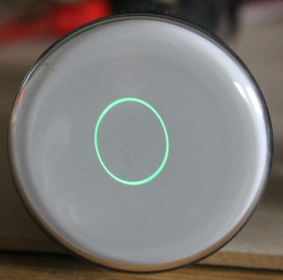
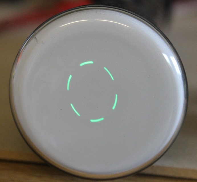
The two photos below show what “in focus” looks like on the actual bench — a CRT lit under test, the spot pulled down to a point:
2.5.3 Astigmatism — and trimming focus against a2
A real gun is never perfectly axially symmetric, and the deflection plates themselves distort the field. The result is astigmatism: the lens focuses the horizontal and vertical directions at slightly different planes, so there is no single focus pot setting that makes a true round point — instead you get a spot that goes from a short horizontal line, through a small blur, to a short vertical line as you sweep focus. The fix is a second degree of freedom: you trim the focus (a1) against the final accelerating anode (a2), adjusting the two together so the two focal planes coincide and land on the screen. In a full oscilloscope this is the “astig” control interacting with focus; on the tester you do it by hand, nudging a1 and a2 until the spot is round and minimal at the same time.
Table 4 — Astigmatism — and trimming focus against a2
| Focus symptom on the tester | Likely cause | What to adjust |
|---|---|---|
| Spot blurs symmetrically, sharpens to a point mid-range | Normal — just find the focus pot sweet spot | Focus (a1) alone |
| Best focus is a short line, not a point; rotates 90° across the sweep | Astigmatism | Trim a1 against a2 |
| Spot never sharpens, hazy/bloomed at every setting | Gas (soft tube) — ionisation defocuses the beam | Nothing fixes it; tube is soft |
| Focus point drifts as brightness changes | Weak gun / low accel — beam-loading pulling the lens field | Raise a2; suspect tired cathode |
Electron-optics obsessives will recognise the family resemblance to how the eTracer and uTracer6 pulsed-HV tube tracers reason about a vacuum device’s internal fields — same physics of electrons in shaped electrostatic fields, just applied to a triode/pentode’s control-grid transconductance rather than a beam-forming lens. If you have spent time reading plate-curve families on those, the einzel-lens intuition here will feel familiar.
2.6 The accelerating anode a2 — beam energy before deflection
The final gun anode, a2, is the tester’s accelerating EHT — up to +2.2 kV. Its job is to give the focused beam its forward kinetic energy before it enters the deflection region. The energy an electron picks up is simply e·V_a2, so the electron velocity entering the plates scales with the square root of a2. That velocity matters enormously for the next stage, because it sets how much time each electron spends between the deflection plates, and therefore how far a given plate voltage can bend it.
This is the crux of the tradeoff you feel at the bench: crank a2 up for a crisp, bright, well-focused spot and you stiffen the beam so the plates deflect it less per volt. Back a2 down for lots of deflection and the spot dims and the gun works closer to its focus limits. The tester lets you set a2 independently and read it on an external kV meter, so you can pick that operating point deliberately for the tube in front of you rather than accept a fixed compromise. Vol 4 covers how the flyback-derived multiplier produces this rail.
2.7 The deflection plates — how the spot moves, and how far per volt
Past a2 the beam is fast, thin, and aimed at screen-centre. Two orthogonal pairs of parallel plates then steer it: the Y (vertical) pair and the X (horizontal) pair. Put a differential voltage across a pair and the transverse field pushes the beam toward the more-positive plate; the beam exits the plate region at an angle and coasts the rest of the way to the screen, where a small angle becomes a large displacement.
The Mark 2 drives each pair push-pull (differentially), ±300 V, with AC-coupled X and Y inputs so an external signal source can sweep the spot into a trace. Push-pull (one plate driven positive while the other goes equally negative) keeps the average plate potential constant, which avoids the beam-energy shift and defocusing you’d get from single-ended drive.
2.7.1 Deflection geometry
        deflection plates                          screen
        (length l, gap d)                            │
   ┌──────────────────────┐                          │
   │  +V/2  (upper plate)  │                          │  ▲
   │══════════════════════│                          │  │
 ──┼──────────╲───────────┼──────────────────────────┤  │ y  (deflection)
   │           ╲__________│ ← beam leaves at angle θ  │  ▼
   │  −V/2  (lower plate)  │        (drift region)     │
   └──────────────────────┘                          │
   │◄──────── l ─────────►│◄──────────── L ──────────►│
                                (L ≫ l typically)

   d = plate gap,  l = plate length,  L = plate-centre-to-screen distance
   V = differential plate voltage,  Va = accelerating (a2) voltage
While an electron is between the plates (length l) it feels a constant transverse field E = V/d, so it gains sideways velocity; after it exits it coasts in a straight line the distance L to the screen. Working the kinematics through and using that the electron’s forward energy is e·Va gives the standard electrostatic deflection result for the spot displacement y:
y ≈ (l · L · V) / (2 · d · Va)
and the more useful deflection sensitivity S — displacement per volt of plate drive:
S = y / V ≈ (l · L) / (2 · d · Va)
Read the geometry straight off it: longer plates (l) and a longer drift (L) both increase sensitivity; a wider plate gap (d) and — critically — a higher accelerating voltage (Va = a2) both decrease it. That last term is the one you own from the front panel:
Higher accelerating anode voltage ⇒ stiffer, faster beam ⇒ less deflection per volt.
Sensitivity is usually quoted the other way up, as volts-per-centimetre (or V/division) — the plate voltage needed to move the spot one cm — which is just 1/S. A small scope CRT might want on the order of 20–50 V/cm; the tester’s ±300 V swing then buys you several centimetres of usable deflection each way.
Table 5 — Deflection geometry
| If you change… | Deflection sensitivity S | Spot brightness / focus | Note |
|---|---|---|---|
| Raise a2 (Va) | falls (∝ 1/Va) | brighter, crisper | The core tradeoff |
| Lower a2 (Va) | rises | dimmer, softer | More throw, worse spot |
| Longer plates l | rises | — | Fixed by the tube |
| Wider gap d | falls | — | Fixed by the tube |
| Longer L (bigger tube) | rises | — | Fixed by the tube |
Because you can independently set a2 and read the plate voltage on external meters, the tester lets you measure a tube’s deflection sensitivity directly: apply a known differential plate voltage, measure how far the spot moves, and compute V/cm on each axis. Doing it on both axes exposes any X-vs-Y asymmetry (unequal plate geometry, or a plate connection problem). This is one of the headline measurements in the closing table.
2.8 PDA — post-deflection acceleration, the key trick
Here is the tension the whole gun design is fighting. You want a bright spot, which means high final beam energy. You also want sensitive deflection, which — from the S equation above — means a low accelerating voltage through the plates. Those pull in opposite directions: accelerate hard for brightness and you kill deflection sensitivity; keep the beam slow through the plates for sensitivity and the spot is dim.
Post-deflection acceleration (PDA) resolves the conflict by accelerating the beam after it has already been deflected. The tube adds a helical (spiral) conductive anode — a resistive coating stripe wound down the flare of the envelope, between the deflection plates and the screen — held at a much higher potential than a2 (the tester supplies up to +5.6 kV for it). The beam passes the plates while still relatively slow (so the plates get their full leverage and deflection sensitivity is high), then the PDA field speeds it up over the final drift so it hits the phosphor with high energy and makes a bright spot.
   Without PDA:                     With PDA:
   plates ──► fast beam ──► screen   plates ──► slow beam ──► [PDA helix] ──► fast ──► screen
             (accel = a2)                       (accel = a2, low)   (+5.6 kV boost)
   bright OR sensitive,             sensitive at the plates AND bright at the screen
   pick one                         — the beam is boosted after it's already been bent
The reason a helix is used rather than a single ring is subtlety about the field: a smoothly-graded resistive spiral produces a gentle, distributed accelerating field over the final drift region. A single abrupt high-voltage ring would create a strong lens right where the deflected beam is fanning out, distorting geometry (barrel/pincushion) and re-focusing errors. The graded helix accelerates without slamming a hard lens across the deflected beam, so the deflection you already set survives to the screen. This is exactly why PDA tubes want a final anode voltage far higher than a2 — the whole point is that the big acceleration happens downstream of the plates, not through them.
Table 6 — PDA — post-deflection acceleration, the key trick
| Parameter | Non-PDA tube | PDA tube (tester’s ≤ +5.6 kV) |
|---|---|---|
| Where the beam gets its energy | All at a2, before the plates | Split: modest a2, big boost after plates |
| Deflection sensitivity | Set by a2 (must compromise) | High — plates see only the low a2 energy |
| Spot brightness | Limited by a2 ceiling | High — PDA adds energy at the screen |
| Final-anode voltage vs a2 | equal (a2 is final) | much higher (PDA ≫ a2) |
| Tester behaviour if PDA too low | n/a | Spot dim but present; sensitivity still OK |
⚠ PDA is the tester’s highest voltage — up to +5.6 kV. A tube specified for more than 5 kV PDA will still show a spot on this tester, but dimmer and softer than nameplate, because the tester’s PDA ceiling is ~5.6 kV (a stated limitation). That is a tester limit, not a tube fault — note it against the reading, don’t condemn the tube.
2.9 The phosphor screen and aquadag
The beam’s journey ends at the phosphor screen — a thin layer of inorganic phosphor crystals coated on the inside of the faceplate. Each high-energy electron that lands excites the phosphor, which relaxes by emitting a photon: that’s the glowing spot. Two properties of the phosphor decide what you actually see, and both are named in the tube’s “P-number”.
2.9.1 Phosphor type and persistence
Persistence is how long the phosphor keeps glowing after the beam has moved on — set by the decay time of the phosphor’s luminescence. It’s the single most visible difference between CRT types on the bench:
Table 7 — Persistence is how long the phosphor keeps glowing after the beam has moved on — set by the decay time of the phosphor's luminescence. It's the single most visible difference between CRT types on the bench
| Phosphor | Colour | Persistence | Classic use — what you’ll see on the tester |
|---|---|---|---|
| P1 | Green | Medium | General scope/indicator; clean green spot, the “default” look |
| P7 | Blue flash → yellow-green afterglow | Long (two-layer) | Radar PPI; a moving spot leaves a lingering yellow trail |
| P11 | Blue | Short | Photographic scope recording; sharp, fast blue |
| P31 | Green (high efficiency) | Medium-short | Modern scope standard; bright, crisp green |
Long-persistence types (P7) will show an obvious afterglow trail as you deflect the spot — normal, not a fault. Short-persistence types (P11, P31) give a crisp spot with no smear. Knowing the tube’s phosphor tells you whether a trail is the tube working correctly or a slow, defocusing gun.
2.9.2 Aluminised screens and the aquadag final anode
Most electrostatic CRTs past the earliest ones have an aluminised screen: a microscopically-thin aluminium film evaporated over the back of the phosphor. It does two jobs — it mirrors light that would otherwise be lost backward out through the faceplate (brighter picture), and it provides a conductive backing that carries beam current away and prevents the phosphor from charging up.
Inside the flare and neck, the glass is coated with aquadag (a colloidal-graphite conductive coating). On the inner surface it forms the tube’s final anode — either the a2 anode or, on PDA tubes, part of the PDA return — and it also serves a quieter but essential role: collecting secondary electrons. When the high-energy beam hits the aluminised phosphor it knocks loose secondary electrons; if these had nowhere to go they would build a negative charge on the screen that repels the beam and chokes brightness. The aquadag coating, at anode potential, sweeps those secondaries up and returns them to the supply, keeping the screen at a defined potential and the current path complete.
⚠ Spot-burn is a real risk on the bench. A stationary, bright, well-focused spot dumps all its energy onto one patch of phosphor and will permanently burn it — a dark spot that never recovers. When testing, keep the spot moving (deflect it, or sweep an X/Y signal in), keep brightness no higher than needed to see it, and never park a bright focused spot at screen-centre while you go read a meter. This is doubly true at high PDA where the spot is brightest.
2.10 What the tester lets you observe and measure
Pulling the whole electron trip together, here is the payoff — the set of things this hand-operated box lets you read off a real tube, and the gross faults each observation exposes. This is the working summary of the volume; Vol 6 turns each row into a step in a bring-up procedure.
Table 8 — What the tester lets you observe and measure
| Measurement / observation | How you get it on the tester | What it tells you |
|---|---|---|
| Cutoff bias | Set accel/PDA; make g1 more negative until the spot just extinguishes; read the grid voltmeter | Gun health + brightness range; scales with accel voltage |
| Focus voltage | Sweep the focus (a1) supply for the smallest spot; read the focus voltmeter | The tube’s a1/a2 focus ratio; a “sweet spot” you can’t find = gas or weak gun |
| Astigmatism trim | Adjust a1 against a2 for a round minimal spot | Confirms clean electron optics; residual line-focus = plate/field asymmetry |
| Deflection sensitivity (V/cm), each axis | Apply a known differential plate voltage, measure spot travel, compute V/cm; repeat on X and Y | The tube’s deflection factor; X-vs-Y mismatch flags plate geometry/connection issues |
| Sensitivity vs accel voltage | Re-measure sensitivity at two a2 settings | Confirms the S ∝ 1/Va relationship; picks the brightness-vs-throw operating point |
| PDA brightness effect | Raise PDA and watch the spot brighten with deflection unchanged | Confirms post-deflection acceleration is working; dim-but-present = PDA below the tube’s rating |
| Low emission | Spot dim even with g1 near cutoff-off and accel/PDA at full | Tired cathode — the headline old-CRT fault |
| Gas (soft tube) | Blue haze in the neck; focus never sharpens; cutoff won’t hold | Loss of vacuum — tube is soft, not repairable |
| Heater-cathode short | Heater and cathode rails interact; bias behaves wrongly; possible hum on the spot | Insulation breakdown between heater and cathode |
| Open heater | Heater draws no current; cathode never lights; no spot at all | Broken filament — dead tube, but an obvious dead, distinct from low emission |
Two things make these measurements possible on such a simple instrument: every electrode voltage is independently set and metered (the tester brings out provision for external current and voltage meters), and the design deliberately gives you wide, overlapping ranges on grid, focus, accel, and PDA so you can find the operating point of an unknown tube by hand. That is the entire philosophy of the Mark 2 — “simple and manually operated, no micro-controller or PC in sight” — and it works precisely because the physics in this volume is stable and legible: warm the cathode, throttle with the grid, focus with the einzel lens, accelerate, deflect, and boost after the plates.
This same beam-in-a-glass-envelope physics underpins the mechanical- and electrostatic-display work in the Television project — the electrostatic CRT is the direct ancestor of the display tube, differing mainly in that broadcast picture tubes went to magnetic deflection and focus (which this tester explicitly cannot drive) while these scope/radar/indicator tubes stayed electrostatic. If you have read the Television material on how a raster is painted, this volume is the close-up on the gun that paints it.
With the physics established, Vol 3 turns to the tester’s own history and lineage — the ad-hoc Heathkit-IP17 rig and scope-clock supply that became the Mark 1, then the Mark 2 — and Vol 4 opens up the circuitry that actually generates each of the electrode voltages you have just met.
Comments (0)