DIY IC Tester · Volume 2
DIY IC Tester — Vol 2: The Design Sketch
A stopgap that tests 2112 RAMs on an XGecu T48 now, then a from-scratch board: per-pin electronics, a shared measurement unit, and a library in plain text.
This is a plan, not a build log. Nothing here has been built or tested yet. Part numbers are starting points, to be checked against data sheets when the schematic is drawn.
2.1 Phase 0: test the 2112s on an XGecu T48
The fastest route to testing the ET-3400’s RAM doesn’t need a new board. The XGecu T48 programmer runs logic tests from a list of steps (“vectors”). The open-source minipro software keeps that list in a plain XML file, logicic.xml (minipro on GitLab). Each vector sets every socket pin at once:
0or1drives the pin LOW or HIGH.HorLexpects the pin to read HIGH or LOW.Zexpects it to be off (high impedance).GandVare ground and supply, andCpulses a clock.
A static RAM can be tested as a long list of vectors:
- A write is two vectors. The first sets the address, puts the data on the four I/O pins and takes write-enable LOW. The second takes write-enable HIGH again.
- A read sets the address and expects the stored value on the I/O pins.
A short script can therefore turn a standard memory test into vectors. March C− writes a background, then walks up and down the addresses reading and inverting each cell. It catches stuck cells, address-decoder faults and most coupling faults. For a 256-word 2112 it comes to about 2,600 memory operations, or roughly 5,000 vectors, plus checkerboard and walking-bit patterns on the four data bits.
To be settled before relying on it:
- The 2112 pinout and timing, read from an Intel data sheet, which then goes into the Library.
- Whether minipro and the T48 accept a test that long. The longest test in today’s file has 42 vectors (the 74168). If there is a limit, the test splits into blocks that each rewrite and re-read their part of the memory.
- Whether a vector’s pin changes happen together. If write-enable could change before the address settles, the write vector splits into three steps (address, then write-enable LOW, then HIGH).
The script will live in this project’s projects/t48-2112/. The same approach covers any small static RAM the T48’s own list leaves out: 2101, 2102, 2111 and 2114.
2.2 Phase 1 onward: a board of its own
2.2.1 The idea in one picture
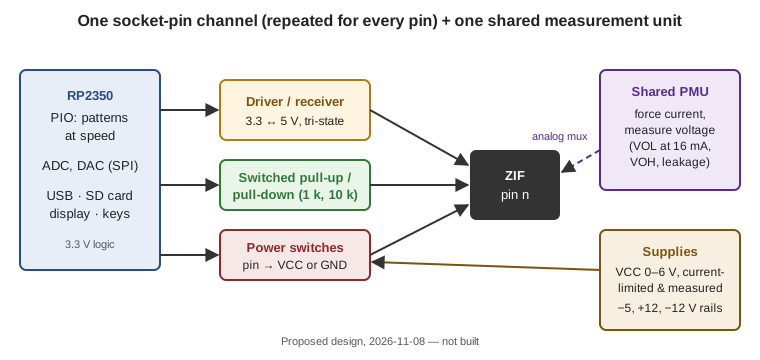
Professional chip testers separate two jobs: pin electronics, which every pin has, and a parametric measurement unit (PMU), which is shared and switched onto one pin at a time. The same split keeps a hobby design affordable.
2.2.2 Per-pin electronics
Each socket pin gets:
- A driver/receiver that translates between the microcontroller’s 3.3 V and the chip’s 5 V, and can go high-impedance. A single-bit translator such as a 74LVC1T45 is the kind of part to start from. TTL inputs need 1.6 mA pulled out of them when LOW, so the driver must sink that comfortably.
- Switched pull-ups and pull-downs (for example 1 kΩ and 10 kΩ). These let open-collector outputs (7403, 7416) read correctly, and they expose floating or leaky pins.
- Power switches, so any pin can be VCC or ground. That is how one socket serves every pinout. For the first 16-pin board a smaller version is enough: fixed positions for the common 14- and 16-pin power pins, plus adapters.
2.2.3 The shared measurement unit
One precision circuit, routed to any pin through an analog multiplexer, makes the electrical checks no cheap tester does:
- VOL: force 16 mA into a LOW output and measure the voltage. Standard TTL must stay under 0.4 V.
- VOH: draw 400 µA from a HIGH output. It must stay above 2.4 V.
- Input threshold: ramp an input slowly and watch the output switch.
- Leakage: measure the current into an input at 0 V and 5 V.
The parts are a digital-to-analog converter (DAC) to set the current, an op-amp current source/sink and an analog-to-digital converter (ADC) to read the voltage. It is slow, a few milliseconds per pin, which doesn’t matter: it runs only after a chip passes its logic test.
2.2.4 Supplies
- VCC: 0–6 V from a DAC-controlled regulator, current-limited and measured. A chip drawing far more than its rated supply current is caught in the first milliseconds, before anything gets hot. Running a test at 4.75 V and 5.25 V checks the TTL supply limits too.
- The old-memory rails: −5 V and +12 V for the 4116, and a −12 V rail for the clock drivers that the Intel 1404A and Signetics 2504 shift registers need. These sit on adapter boards rather than on every pin, which keeps the main board simple and safe.
2.2.5 The brain
An RP2350 (the Raspberry Pi Pico 2’s chip). Its PIO blocks can play test patterns into the socket and sample the outputs with nanosecond-scale timing, independent of the processor. That makes at-speed tests possible: apply an input edge and check that the output has changed within the data sheet’s propagation delay. The rest is ordinary: USB for a PC, an SD card for the library and logs, a small display and a few keys for standalone use.
2.2.6 The library
One small text file per part (TOML or YAML), written from the data sheet of the actual part, never from a different family’s number. Each file holds:
- the pinout and supply pins;
- the logic vectors (or, for a RAM, the memory size and the test to run);
- the electrical limits (VOL, VOH, supply current, propagation delay).
Kept in git, a mistake can be traced and fixed. Anyone can add a part without touching the firmware.
2.2.7 Case and socket
A handheld or small diecast enclosure (Hammond makes both) or a 3D-printed case. A genuine 3M Textool ZIF socket costs more than any other single part on the board, and is worth it. Cheap ZIF sockets wear and lose contact, and the EEVblog users quoted in TSH-06F Vol 4 traced test errors to chips seated off-centre.
2.3 The phases
Table 1 — The phases
| Phase | What | Tests | Needs |
|---|---|---|---|
| 0 | T48 + generated vectors | ET-3400 2112s; KENBAK-1 7451/7454 and open-collector parts with the T48’s own tests | A T48, a script |
| 1 | 16-pin board: logic, pull-ups, fixed power pins | KENBAK-1 TTL and 2112s on my own hardware | Schematic, PCB, firmware |
| 2 | Add the measurement unit and programmable VCC | VOL/VOH, supply current, voltage margins | Analog design, calibration |
| 3 | 1404A/2504 adapter | The KENBAK-1’s 1404A spares | −12 V clock drivers, data sheet timing |
| 4 | 40 pins, power on any pin, DRAM adapter | 4116/4164, larger chips | More channels, the −5/+12 V adapter |
Each phase is useful on its own, and each is a natural volume of this dive once it is built.
Comments (0)